Wednesday, 13 August 2025

Republishing a WS2812 PSoC Creator Project

Introduction 
This short blog republishes a PSoC Creator project that uses a WS2812 component. The WS2812 is an addressable RGB LED, as seen in common devices such as LED strips. The original post with the PSoC Creator Project, ‘WS2812 and 5LP @ 48 MHz’ was posted in the Infineon Developer Community with the project named ws2812_test.cywrk_.Archive01.zip.

Reason to Republish
Four development boards, the micro:bit, Arduino, PSoC, and STM, were chosen for comparison. Most of those boards have been or are currently used in education, and they have a broad sample of projects with code spread across community forums and sites.

Project Example to Compare Development Boards
The addressable RGB LED (WS2812B) was chosen as the example project since LED strips are engaging with students. Example projects were found for all but the PSoC4 part 
CY8C4245AXI-473. The Modus Toolbox PSoC development environment from Infineon supports NeoPixels, but an example did not seem to be available for the PSoC4. The target audience for this project was at the education level, so off-the-shelf and ‘working’ examples were preferred.

Using Modus Toolbox, the CY8C4245AXI-473 PSoC microcontroller was not listed under the ‘Select device part numbers'.

Modus Toolbox BSP Assistant - Device Part Numbers

A related development kit, CY8CKIT-042, associated with the same PSoC4, was not listed under the Modus Toolbox ‘Select BSP template’.

Modus Toolbox BSP Assistant - Template

Understandably, the target PSoC is an older device, so some limitations were anticipated. Of course, a PSoC6 development kit could be used with the NeoPixel LEDs, but that was hardly a fair comparison against the slightly slower micro:bit or Arduino.

Finding a WS2812 PSoC4 Example Project
A WS2812 library was available for PSoC5, 
CY8C5888-LP097, by the author, Mark Hastings (Cypress Semiconductor). The example project for the WS2812 was taken from the Infineon community forum, but the project is several years old and contains broken component dependencies.

Later, I was to find another PSoC WS2812 project from the same author called FunWithLEDs. This project contains comprehensive examples of the WS2812.

Rebuilding the WS2812 Example Project
Opening the Top Design in the WS2812 PSoC5 project, some missing components were shown.

Missing Components in PSoC Top Design

The missing library was not included with the WS2812 project, so this was found on another site and copied into the project's root folder.

Added WS281xlib to Project Folder

To correct the missing library component in the PSoC project Top Design, the Dependencies menu in PSoC Creator was used to perform an update.

PSoC Creator Dependencies - StripLightLib Error

The existing dependency for the WS2812, called StripLightLib, was removed.

Lastly, the dependency for WS281xLib was added to the project dependencies, now pointing to the copy in the project’s root folder. 

PSoC Creator Dependencies - WS281xLib

The downloaded WS281xLib contains the StripLightLib library and several others worth exploring.

Contents of WS281xLib Folder

The missing component issue was resolved in the projects Top Design, as pictured below.

Updated Components in PSoC Top Design

Compiling the project resulted in no further issues.

Complied QS2812 PSoC Creator Project
Complied WS2812 PSoC Creator Project

The PSoC target was changed to the CY8C4245AXI-473. Finally, the development board was programmed and subsequently used for the development kit evaluation.


Downloads
The dependency WS281xLib and the updated project for PSoC5, built for PSoC Creator 4.4, are available below for download. All intellectual property rights and licenses for the libraries and PSoC Projects, including those belonging to Mark Hastings, Cypress Semiconductor, and related parties, are retained and owned by those entities.

WS281xLib
WS281xLib

ws2812_test
ws2812_test

Thursday, 31 July 2025

Drill Press Controller Update Part 2

Introduction 
This blog details the completion of the drill press controller's printed circuit board (PCB) layout, a partial build of the power supply and testing.

Model of ESTOP PCA Mated to the Enclosure

Placement of New Components
In the previous post, the PCB shape was defined to suit the enclosure. In this post, the component placement and board routing were performed. Even though the design has a relatively low component count, attention was still paid to the mains (AC-DC) power supply and the low-voltage signals. Isolation and component clearances were made a priority.

Unrouted ESTOP Controller PCB

In the above capture, the AC to DC power supply (PSU1) is located on the PCB's left side. The right side of the PCB contains low-voltage parts, such as the microcontroller, input and driver devices.

Unpopulated PCB Housing
After the component placement was finalised, a 3D model of the PCB was generated using the PCB design software. This approach was taken to check for mechanical interference between the PCB and the enclosure model. The check between models was achieved using Fusion 360.

PCB Mated with Enclosure Base

 The design uses the connectors provided with the enclosure.

PCB Mated with Enclosure Base and Cover

With no interference detected between objects, the PCB was routed.

Routed PCB and Layers
The PCB was designed using a standard 4-layer 1.6 mm PCB stackup provided by the manufacturing house.

PCB Top Layer
PCB Top Layer

PCB Mid Layer 1
PCB Mid Layer 1

PCB Mid Layer 2
PCB Mid Layer 2

The PCB bottom layer was a copper fill under the low-voltage section and not shown in this post.

Manufactured PCB and Population 
To populate a new PCB, I prioritise installing the power supply first. However, as the controller PCB is double the size of the reflow device (e-Design Miniware MHP50), more difficult parts were soldered first.

Reflow Part on a MiniWare

The driver chip with an exposed pad was reflowed first.

Power Supply Population
Next, out of the two onboard power supplies, the discrete switch-mode DC 5 V regulator was fitted to the board.

Power Supply Bench Test

Testing was performed by directly supplying power to the relevant connections on the board. The turn ON voltage was noted at 6.8 V with the unloaded accuracy better than 2 %. With a 165 mA resistive load, the voltage regulation was better than 0.6 %. However, with a 330 mA load, the voltage regulation fell to 3.6 % which was likely due to the inductor. A different inductor will be tested in the next post, together with the additional PCB components.

Sunday, 29 June 2025

Salvaging Components from an Atom LED Baton

Introduction 
This brief blog details the salvageable components from the circuit boards of a mains-powered LED light baton manufactured by ATOM.

ATOM Baton Nameplate

Attempting a Repair
When the LED baton, Atom part #AT9877, initially failed to switch ON, the initial thought was that a repair should be possible. Disassembling the unit and checking the control board revealed some damaged resistors.

Damaged Resistors on Circuit Board

After replacing the resistors and retesting the baton, it became apparent that multiple components on the board had failed. The additional failed components included the main switching FET and, after a subsequent test, the onboard fuse. Although a repair seemed feasible, reliability was in question, so the part salvage route was instead chosen. 

Parts Salvage
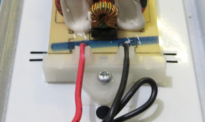
As the baton was already partially disassembled, the control board was easily removed. Two plastic holders were fitted to the ends of the board, and then those clips were fixed into the baton’s metal housing. The board mounting solution is an interesting alternative to mounting holes, which are usually included on circuit board designs.

Plastic Circuit Board End Clips

The wires to the control circuit board were cut, and the control board assembly was removed. Remaining fitted to the baton's chassis, which could be salvaged, were solid core mains cable, the LED boards and some fixings, including terminal blocks.

Each of the two LED boards was fixed in place with seven plastic pins, as shown in the image below. The clips were removed by pushing them from the other side of the baton. 

Plastic Clips Holding LED Circuit Boards to Baton Chassis
Plastic Clips Holding LED Circuit Boards to the Baton Chassis

The 60 LEDs per board were checked using the diode test on the multimeter; both LED boards could be salvaged or kept for similar LED baton repairs.

LED Strip Markings
LED Strip Markings

Turning attention back to the control circuit board, this was a double-sided (population) design. The control board consisted of surface mount parts on the copper (solder) side and through-hole components on the opposite side. Surface-mount parts were held to the circuit board with an epoxy adhesive, such as the Chip Quik AD1-10S or Henkel Loctite 3621, making reworking or salvaging parts difficult. The benefit for the manufacturer, however, is that this design results in a simplified process during soldering (usually reflow).

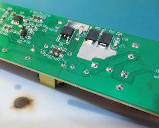
Baton Control Board - Solder Side

If easily removed, the diodes (red box in the solder side image) can be salvaged from the solder side of the circuit board. The two larger rectifier diodes marked as US5M are from the manufacturer Suntan.

A datasheet for the main switching FET (yellow box 
in the solder side image) could not be sourced, and the part number for the 8-pin controller was not easily readable.

Baton Control Board - Top Side

Reviewing the through-hole component side of the control board, the combination of six inductors and chokes (purple boxes in top side image) could be salvaged with minimal risk of damage.

The bridge rectifier (green box) from NextGen components, part KBP210, could be removed and tested.

The manufacturer for the majority of the electrolytic capacitors (red boxes) was Axboom. The three large mains rated 47 uf 350 V devices showed no signs of damage or bulging and could be salvaged. 

Long or larger components, such as the capacitors on this board, are secured with white glue or silicone, although this material can easily be cut off.

There is a safety capacitor (blue box) on the board marked with JNC, JY332M; a datasheet could not be found. This appears to be a 400 V AC 0.0033uF Y5U capacitor, and although the Y5U specification drifts when the temperature changes (image below), the part may be useful for other designs or repairs.

Example - Y5U Safety Capacitor vs Temperature

The varistor (black box) on the AC supply appears to be from SONGLONG LISHANG, part 07D471K. This varistor could be tested and used for repairs.

Although the fuse was damaged on this baton, Littelfuse TE5® 392 series markings T1AL250V, it could be salvaged on a working control board.

Saturday, 31 May 2025

Dill Press Controller Update

Introduction 
This blog details improvements to a drill press controller created in a previous blog.

Why an Update?
With features such as sensing a stalled chuck, the drill press controller project was something of an experiment for home. Enquiries to this day persist for a ‘user-friendly installable’ version of the drill press controller. As many users seem to prefer a ready-to-go solution, the circuit board change in this post is a step towards simplifying the original controller design, but with some experimental improvements.

What Consolidation and Improvements?
The external DIN rail DC supply from the previous design could be incorporated onto the updated controller board. To fit an AC to DC module to the controller board, however, the controller enclosure would need to be changed from the original type.

Additionally, the AC contactor, which disables the drill press motor when an ESTOP event occurs, was identified as a space-consuming item. A subsequent post will review SSR (Solid State Relay) testing and, if useable, replacing the contactor.

Changes to the Design
Integrating an AC to DC supply onto the circuit board raised some technical questions. Firstly, what voltage should the DC output be? The second question is whether the voltage is suitable for other components in the system. Included in the list of other components are the SSR inputs and existing hardware, such as the ESTOP pushbutton LED.
For testing, a high-current dual form A SSR TE part (SSRD-240D25) was chosen.

TE SSRD-240D25 Solid State Relay

New Enclosure
Using the circuit board dimensions from the original controller as a guide, an enclosure from the manufacturer, Phoenix Contact, part 1311009 (BC 107,6-KIT-U11-7035+4SPTA12), was chosen. This part was selected because it was a two-part case with circuit board mounting, supplied with terminal circuit board terminals, and was affordable.

Phoenix Contact Enclosure #1311009

Schematic Changes
An AC-DC brick from Vigortronix was selected with a DC 12 V output. The VTX-214 series is manufactured with several DC output voltage options.

Updated Power Supply Schematic

As an experiment, a single input PLC device from Maxim was chosen to replace the previous input circuit.

Updated Input Schematic

In the previous design, the contactor coil was powered by two driver chips. For the updated design, the output was changed to instead drive the two enable inputs of the SSR or a similar device.

Updated Output Driver Schematic

Circuit Board Size and Shape
The technical datasheet for the 
Phoenix Contact enclosure does not appear to provide a dimensioned circuit board example. However, there is sufficient information in the technical drawing to define the circuit board shape. In fact, the 3D model of the enclosure from the Phoenix Contact website also contains an excellent example of circuit board mounting options. In the image below, Fusion 360 was used to hide the outside case of the enclosure.

Example of Circuit Boards in Phoenix Contact STEP Model

To validate the circuit board shape in the circuit board design software, the Phoenix Contact STEP model was required without all the example board options. Fusion 360 was used to suppress all but the plastic base in the STEP file. This STEP file was imported into the circuit board software to validate the circuit board shape.


Example of STEP File Imported into Circuit Board Design Software

In the next blog for the updated controller, the PCB layout is completed.

Wednesday, 30 April 2025

Model Rocket Launcher WiFi ESP8266 Part 4

Introduction 
This blog is a brief update following on from Part 3 of the ‘Wi-Fi-controlled rocket launcher’. A design to replace the lead-acid battery in the launcher was assembled. 

Some field shots of the updated launcher are provided at the end of the post.

18650 Replacement for Lead Acid Battery
A printed circuit board (PCB) with two 18650 batteries was designed
to replace the 12 V lead-acid battery used by the launcher.

The operating voltage of the launchers' ESP32 controller and the output drivers is around 3.3 V, meaning the parts were suitable for operation with the 18650 voltage. However, the main DC-DC converter (LMR50410YFQDBV) would need to be changed or bypassed, as its operating voltage is 4 – 36 V. The standard operating voltage of a single 18650 cell drops below the 4 V threshold of the DC-DC converter.

The Keystone Electronics 18650 battery holder, part #1043, was chosen for the PCB design. When selecting parts in the initial PCB layout, two 1043 battery holders were more cost-effective than a double 1850 holder, Keystone part #1049. The Keystone double battery holder had become the cheaper option at the time of writing.

Dual 18650 PCB
Dual 18650 on PCB

The dimensions of the PCB were made to fit into the existing 3D printed launcher case.

Dual 18650 PCB in 3D

After the PCB was manufactured, a single Keystone battery holder was fitted. For connection compatibility with the spade tabs on the lead acid battery, spade connections were fitted on the PCB using TE Connectivity part #60465-2. As can be seen in the image below, the spade connections were secured to the PCB with M3 mounting hardware.

Partially Populated 18650 Board

Out of curiosity, the DC-DC converter on the launcher was run from a single 18650. First, the previous voltage divider created by the resistor pack RP1 was removed. The shutdown input on the DC-DC converter (LMR50410YFQDBV) was then connected to the supply (VIN) with a 10 R resistor.

Existing DC-DC Converter Shutdown Circuit
 
Modified DC-DC Converter Shutdown Connection

Using a fully charged 18650, the launcher powers ON briefly. When the 18650 voltage drops below 4 V, the DC-DC converter fails to turn ON and the output voltage becomes unstable. Having the PCB with different 18650 connection options may be part of the next board review.

Field Tested Unit

The two launches below are taken from a recent rocket day.


Sunday, 30 March 2025

Salvaging Components from DPF-HD1000

Introduction 
This post looks at electronic components that could be salvaged from a Sony digital photo frame, DPF-HD1000 (circa 2010).

Tear Down
Four plastic screws secure the two halves of the photo frame case. A thin prying tool was used to release the internal plastic clips.

DPF-HD1000 Front Cover Removed

Removing the front panel shows the LCD and two peripheral items, an IR sensor and an LED strip.

Internals of the Photo Frame
Shifting the position of the display shows the main Printed Circuit Assembly (PCA) and the board to peripheral connections.

DPF-HD1000 with PCA Exposed

The IR receiver was connected with a 3-pin cable to the main PCA. The markings on the sensor appear to be 28m5 and E23, but there is no data available for the part online. The connections to the sensor could possibly be determined from the cable colours.

DPF-HD1000 LED Logo Board

The small LED PCA was labelled ‘logo LED board’ circa 2011. This board was used to illuminate the Sony logo built into the front plastic cover.

DPF-HD1000 LED Logo Board Powered

From the website Panel Look, the LCD appears to be from CPT, although discontinued, and could be used for repair or paired with a converter board capable of driving 60-pin flat flex cables from various interfaces such as USB.

DPF-HD1000 LCD Part Number

After removing the 4 screws retaining the PCA, the entire electronic assembly could be removed.

DPF-HD1000 Complete Electronics Assembly

Disconnecting all the peripherals from the PCA, attention turned to some interesting components on the main PCA. The PCA was labelled ‘Sony Basic 10DW MP’.

Possible PCA Component Salvaging
The USB connectors, surface mount and vertical switches could be salvaged from the PCA. The combination card holder on the PCA was an interesting component (large component on the right of the PCA); no data could be found from the A238B marking on the device.

DPF-HD1000 PCA Side 1

Upon reviewing the passives, inductors and the common mode filter near the DC jack (bottom right) these could be salvaged and reused. Due to the age of the PCA, the SMT electrolytic capacitors are not recommended for salvaging, although they did appear in near-new condition.

For active devices, the single linear regulator 1117T near the SD card holder could be salvaged.

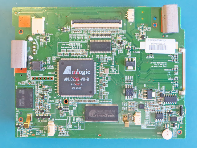
DPF-HD1000 PCA Side 2

Flipping the PCA shows several chips, connectors for the peripheral devices and a smattering of passives. If any external devices, such as the IR sensor, were earmarked for salvage, the surface mount connectors could also be salvaged from the PCA.

To the left of the main Amlogic controller is a surface mount switch which may be responsible for detecting rotation (movement) of the display. When shaking the PCA, the internal mechanism can be heard moving. The component marking is EnSky, however no data could be located on the switch.

There is an oscillator, possibly 24 MHz (middle PCA), driving the Amlogic controller and a watch crystal for the on-board RTC (PCA bottom right) that may be useable.

An ELNA button supercapacitor, rated at 3.3 V 0.22 uF, provided backup for the RTC. Looking at the supercapacitor, corrosion was sighted on the case of the device and therefore not useable.

Corrosion on Supercapacitor

The main controller AML6236-VB-B is not listed on the Amlogic website and is likely not worth salvaging.

For storage, Sony opted for a Samsung 2 GB eMMC, part number KLM2G1HE3F-B001 (far left on PCA2). While this component does not appear to be manufactured any more, it would be a great device for experiments. The PCB model still appears to be available (SnapEDA). Even though the component may need to be reballed when fitting the component to a new PCA, connection to micros such as ST or Microchip would most likely be possible.

The 512 Mbit DDR1 memory was provided by Etrontech, part EM6AB160TSD-5G. This part could be used for repairs.

Interfacing the Amlogic controller to the LCD was a Texas Instruments flat panel driver part number SN75LVDS83B. The datasheet is an interesting read and even contains a good summary of PCB layout techniques.

Some other active components on the PCA are the serial flash, switching and linear regulators, speaker driver and RTC. There is also an unmarked chip on the board whose purpose is not clear. Many of these components could be salvaged depending on requirements.

Component Salvaging Example
Often questions posted after salvaging blogs relate to how components are removed from PCAs. As an example, consider the removal of the DC jack from the PCA.

Setup for Component Removal

The jack component is a 5-pin device that could be desoldered although in this example it was removed using a heater plate. Firstly, all the components on the opposite side of the DC jack were removed. These components consisted primarily of passives. This side of the board was made as flat and clean as possible. Then a heater plate, in this instance a MiniWare MHP50, was used to preheat the side of the PCA where the passives were removed (beneath the DC jack). Shortly after the heating cycle, a reflow cycle was run to pry the jack from the PCA. This technique certainly cannot be used for every board and component as the component population density and board construction can have significant effects on heating.

Salvaged DC Power Jack

Other tools such as a hot air desoldering tool or a small temperature controlled oven may be better suited for the removal of specific components.