Summary
This blog reviews GPIO configurations for unused PSoC microcontroller pins with a focus on the resulting differences in current usage. |
| Cypress PSoC4 Controller |
Information relating to the handling of unused pins can be located for most microcontrollers, for example AVR or Microchip. Companies such as Analogue Devices have posted similar unused pin information in their monthly Analog Dialogue.
Between the Cypress Technical Reference Manuals (TRM) and the Cypress community forum, methods for handling unused processor pins have been detailed or discussed in numerous times. Forum suggestions for managing unused pins varies from configuring the pins as high impedance digital inputs, to resistive pull-up/pull-down to outputs.
The PSoC4 TRM states on page 64 under the High Impedance Analogue heading that unused GPIO pins should be configured as high impedance analogue pins (PSoC 4100/4200 Family PSoC 4 Architecture TRM, Document Number: 001-85634 Rev. *H).
While the TRM does not detail the benefits of terminating unused pins with pull-up / pull-down resistors or the effects of EMC / EMI on floating pins, one of the salient remarks in the extract from the TRM is 'unused GPIOs must be configured to the high-impedance analog'. The previous comment relates primarily to current consumption in low-power modes, however the pin configuration could be inferred for unused pins.
High-Impedance Analog
High-impedance analog mode is the default reset state; both output driver and digital input buffer are turned off. This state prevents an external voltage from causing a current to flow into the digital input buffer. This drive mode is recommended for pins that are floating or that support an analog voltage. High-impedance analog pins cannot be used for digital inputs. Read-ing the pin state register returns a 0x00 regardless of the data register value. To achieve the lowest device current in low-power modes, unused GPIOs must be configured to the high-impedance analog mode.
For pins configured as high impedance (digital), Electronic Design is one of the sites which details the reason why high impedance digital inputs are not preferred. An extract from the Electronic Design site is detailed below.
Over time, however, the floating input tends to accumulate a charge and float toward the logic level change-over point. When it reaches that point, it causes both the high and low MOSFETs to be partially on, resulting in shoot through current.
To provide a visual representation of shoot through current mentioned in the above extract, consider a post such as this from the Texas Instrument forum.
 |
| Shoot Through Current - Courtesy Texas Instruments |
Certainly other technical sources indicate that pin configurations should be resistively biased or configured as outputs only. Time to perform a few measurements to verify the pin configurations!
PSoC Current Measurements
To perform current measurements of the PSoC4 on the bench, a surplus PCB from a previous project was loaded with minimal components. A PSoC4, a pull-up resistor for the reset line and some essential capacitors were fitted to the board.
 |
| Cypress Microcontroller with Unused Pins |
PSoC Programming was performed using a Miniprog.
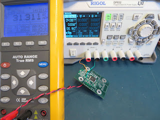
The supply (5 VDC) was provided from a bench supply, Rigol DP832, as shown in the image below. Current measurement was made using a standard digital multimeter.
 |
| PSoC4 Bench Setup for Current Measurement |
The PSoC Creator application used the pin component to configured the entire port. Any change made to the pin type was reflected for all pins on the port.
 |
| PSoC Creator Top Design All Pin Configuration |
Two current measurements were taken as verification. The power supply current measurement was verified against the multimeter.
Measurement Results
Measurements were performed on a PSoC4 (CY8C4245AXI-483) with GPIO drive modes (type) 0 - 4 and 6 - 7.
 |
| PSoC4 GPIO Drives Modes - Courtesy Cypress Semiconductor |
 |
| PSoC4 Overall Current Measurement for GPIO Configurations |
The High Impedance Digital Input GPIO type had a striking difference in measured current compared to the other types.
Final Thoughts
High Impedance Digital Inputs resulted in the highest overall current consumption of an active PSoC4 device. From the brief range of measurements performed in this post it would be prudent not to configure unused PSoC pins as High Impedance Digital.
Unused PSoC pins should be configured with internal resistor biasing or as outputs where practicable.
PSoC Project
For readers interested in verifying or disprove this post, the PSoC Creator project is made available.
 |
| PSoC Creator Project - Test PSoC |
