Introduction
This blog follows the redesign and development of a model rocket launcher controller that features WiFi communications to control the launch process. This design uses an ESP-based microcontroller module. The Arduino platform was chosen for code development.
 |
| Rocket Launcher 3D Model |
Redesign
To control the launch in the previous model rocket launcher design, Bluetooth communications were used between a PSoC microcontroller and an Android phone. The interface was changed to WiFi to remove the need for developing a phone application. Controlling a rocket launch through WiFi would be independent of a phone or computer operating system.
WiFi Module
For the launcher redesign, an off-the-shelf ESP module capable of WiFi was chosen from Adafruit. The ESP module was chosen for a few reasons. Firstly, the module’s price was relatively low (USD 10). The module was readily available compared to other dedicated microcontrollers. Lastly, using an ESP module meant that the rocket launcher design could be migrated more easily to other ESP devices.
 |
| Adafruit Huzzah ID 2471 (Courtesy Adafruit) |
Reused Design
The same section of circuit responsible for driving the rocket engine igniter was taken from the previous design. This section consisted of high (VN7040) and low-side (VNL5030) switching drivers (ST Microelectronics).
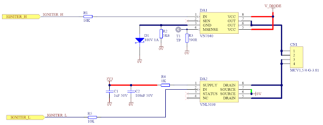 |
| Rocket Launcher Igniter Drive Circuit |
Circuit Updates
To begin the schematic update process, the ESP module was created in the schematic libraries. The new part replaced the previous PSoC microcontroller and associated circuitry.
The Altium PCB model was downloaded from the website SnapEDA.
| Capture of Adafruit Huzzah PCB Footprint from SnapEDA |
Schematic Updates
On the ESP module schematic page, the power supply connections and ST driver control signals were mapped to the ESP.
 |
| Rocket Launcher - Huzzah Circuit Connections |
Audible notification of an impending launch was retained using the buzzer. Connections were mapped to the ESP.
 |
| Rocket Launcher - Buzzer |
The display (LCD) was infrequently used in the previous design so it was removed and replaced with an LED.
The launch button input to the ESP module was retained for testing purposes.
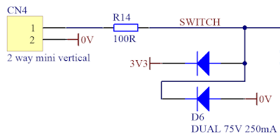 |
| Rocket Launcher - Optional Launch Button |
Connections were made to ESP module pins that had no special functions.
Output Drivers
Schematic changes were made to the ST output driver’s power supply. This was required to match the ESP module’s DC 3.3 V supply voltage. The feedback monitoring from the ST drivers was removed from the design because of the reliable performance of the ST drivers.
Power Supply
A DC-DC step-down converter was retained for the power supply. Texas Instruments part LMR50410 featuring an integrated diode was selected to replace the previous DC-DC converter.
Another benefit of the DC-DC converter is its operating voltage which is wider than the ESP modules linear regulator (LDO). The LDO has a maximum rated input voltage of DC 6 V. This voltage does not suit all battery chemistry types.
Rocket Launcher - Power Supply
Battery voltage monitoring using the ADC on the ESP through a resistor divider was kept for experimentation and possible future use.
Circuit Board
There were no caveats defined for the shape of the circuit board (PCB). The placement of components drove the PCB shape. Minimal design constraints for the PCB meant that the PCB was set up for components on both sides.
The capture below shows the PCB top layer with the ESP module, power supply underneath the ESP module, buzzer and optional screw terminals. To fit the power supply beneath the ESP module, pluggable headers were utilised to space the ESP module off the board.
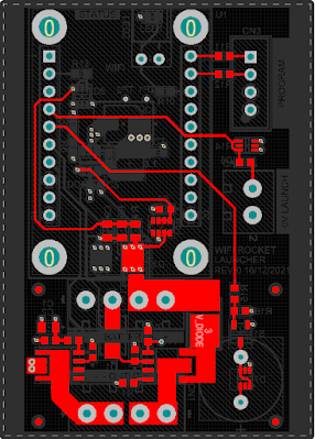 |
| Rocket Launcher PCB - Top Layer |
The next capture below shows the PCB bottom layer containing the output switching drivers and related components.
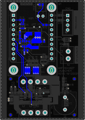 |
| Rocket Launcher PCB - Bottom Layer |
Four PCB layers were used for the launcher board stack-up. Captures of the two internal power planes have not been shown.
After component placement and routing, the board size reached a comfortable size of 62 x 44 mm. On the longest PCB axis, a set of 3 mm strips were added to suit mounting in an enclosure. Pictured below is a 3D side and rear view of the board.
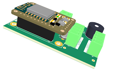 |
| Rocket Launcher - 3D Side View |
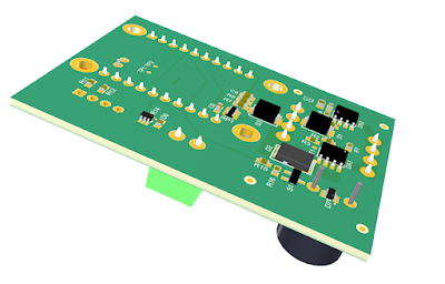 |
| Rocket Launcher - 3D Rear View |
In part 2 of the launcher blog, the PCB construction and initial testing will be performed.
