Introduction
This blog provides two methods for connecting an EPEVER MPPT with RS485 capability to a Windows PC running Solar Station Monitor.
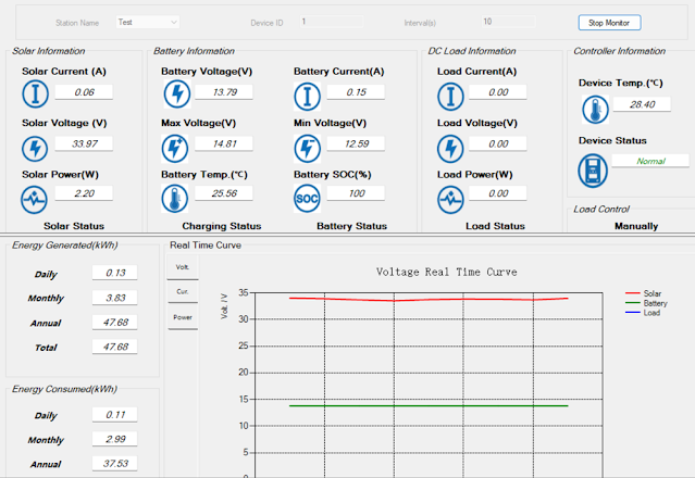 |
| EPEVER Solar Station Monitor |
Direct Connection
Direct connection utilises hardware consisting of an FTDI USB to RS485 adaptor, part USB-RS485-WE with an RJ45 male to screw terminal adaptor to connect to the EPEVER MPPT.
Details for the various connections using the FTDI adaptor are pictured below.
RS485 connections A, B and 0 V were used; no termination resistor was added to the circuit.
 |
| FDTI RS485 to EPEVER MPPT |
Wired USB FTDI to RJ45 adaptor.
 |
| FDTI RS485 to RJ45 8-Way Screw Terminal for EPEVER MPPT |
FTDI adaptor wiring from USB-RS485-WE manual.
 |
| USB-RS485-WE Connections (Courtesy FTDI) |
Pinout for RJ45 connector.
 |
| RJ45 Pinouts (Courtesy Huawei) |
There were no requirements to change the Windows setup for the FTDI adaptor. This device appears as a standard COM port. This COM port was then selectable in the EPEVER Solar Station Monitor application.
Wireless Connection
The wireless connection makes use of an Elfin EW11A. This device bridges RS485 and wireless station and or access point.
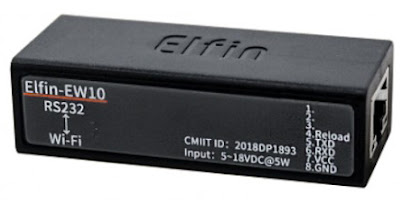 |
| Elfin EW11A (Courtesy Hi-Flying) |
Also used in the hardware solution was the optional Elfin adaptor cable. For connecting to the EPEVER MPPT, an RJ45 male to screw terminal adaptor was utilised. Since the EW11A requires DC 5 V, an further connection to a power supply is also required.
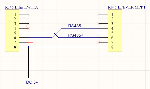 |
| Elfin EW11A to EPEVER MPPT |
 | |
|
The computer running EPEVER Solar Station Monitor required a software Ethernet to COM port bridge. The HW Virtual Serial Port application from HW-Group was used.
Side note. The EPEVER WiFi 2.4 G RJ45 A adaptor was tested separately however because WiFi Station mode was required, the EPEVER was not suitable.
Elfin EW11A Setup
This tests in this blog were geared towards verifying that wireless communications with the MPPT were practicable. The final goal was to interface the EPEVER with Home Assistant.
Using the I.O.T Workshop application from High-Flying, the EW11A was configured for station mode, TCP server and the port settings were configured for consistency with Home Assistant. Ethernet port number 8899 (MQTT) was used. The Comment and Application Guide from Eniris was used as the primary reference document.
Removed from the screen capture below are the login details (admin and password), wireless station ID and associated password.
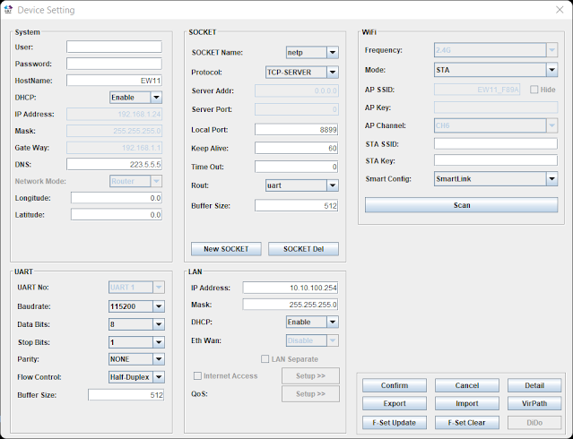 |
| EW11A Device Setup for EPEVER MPPT Using I.O.T Workshop |
No UART protocol was selected. Telnet was disabled and web interface was kept enabled.
 |
| EW11A Device Detail for EPEVER MPPT Using I.O.T Workshop |
The UART settings 115200, 8, N, 1 were left as default.
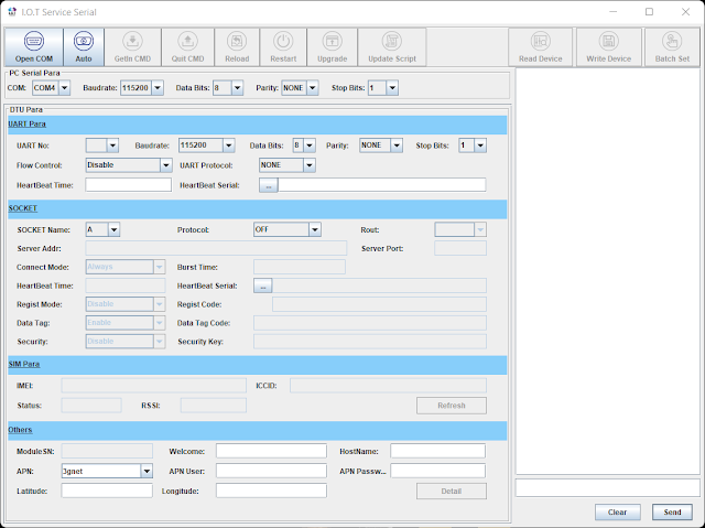 |
| EW11A Serial Setup for EPEVER MPPT Using I.O.T Workshop |
Virtual Serial Port
For this blog the HW Virtual Serial Port application from HW-Group was used. The default configuration of the application required changes. For example, if the option Network Virtual Terminal (NVT) was enabled, communications with the EPEVER MPPT were sporadic or only specific values were received correctly. Other tools offering an Ethernet to COM virtual com port may offer similar configuration options which should be validated.
 |
| HW Virtual Serial Port Settings for EPEVER MPPT and Elfin EW11A |
Shown on the Virtual Serial Port page is the IP and port for the Elfin EW11A.
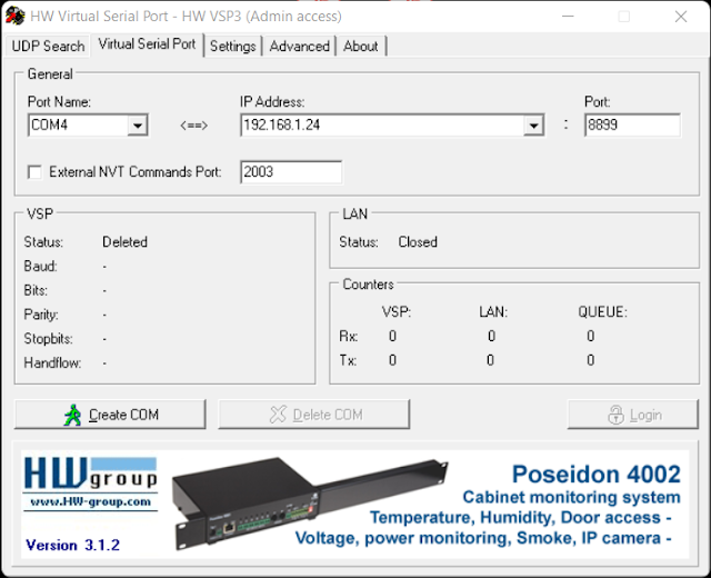 |
| HW Virtual Serial Port Page for EPEVER MPPT with Elfin EW11A |
With the Elfin EW11A configured and powered, clicking Create COM in the virtual serial port application established the Ethernet link. Shortly after COM4 appeared in Windows Device Manager.
 |
| Serial Port Created Using HW Virtual Serial Port |
With a connection established to the EW11A and the EPEVER MPPT, the EPEVER application could communicate with the MPPT. This was indicated by the change in counter values (Rx and Tx).
 |
| HW Virtual Serial Port Connected to EPEVER MPPT with Elfin EW11A |
Solar Station Monitor
No changes were made to the setup of the EPEVER Solar Station Monitor application other than configuring the required COM port to communicate with the Virtual COM port. The default port settings were used.
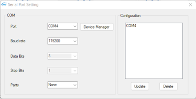 |
| EPEVER COM Port Settings |
After clicking Start Monitor in the application, data was exchanged within a few seconds.
The capture below was taken after sunset with the MPPT load active.
 |
| EPEVER Solar Station Monitor (Load Active) |
The capture below was taken during sunlight hours.
 |
| EPEVER Solar Station Monitor (During Daylight) |
For the capture below, the EPVER monitoring tool was restarted to capture the transition between load OFF and ON.
 |
| EPEVER Solar Station Monitor Graphed Data Showing Load ON |
 |
| EPEVER Solar Station Monitor Graphed Data Showing Load OFF |
Final Thoughts
This post offered two methods for connecting an EPEVER MPPT with a Windows PC running Solar Station Monitor application. The WiFi connection and subsequent testing using the Elfin EW11A served as preliminary work to develop a dedicated circuit board to bridge the EW11A with the EPEVER MPPT.

No comments:
Post a Comment