This blog continues a previous Design for Repair post with a few further examples which may be applied when designing a Printed Circuit Board (PCB) for repair or serviceability.
Debugging Interfaces
For projects containing devices with firmware or configurable logic such as a microprocessor or FPGA (Field Programmable Gate Array), the capability to debug the design during the design phase is considered necessitous. Customarily programming or debug connections are not available for the end-user or customer, however, this interface can be an effective tool for repair.
Examples of programming interfaces are JTAG, SWD and UART
 |
| JTAG 10-Pin. Courtesy Keil |
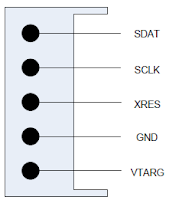 |
| Cypress MiniProg SWD. Courtesy Cypress |
In place of physical connectors such as a pin header, the PCB can incorporate connections using tinned copper or gold fingers when cost saving on components is critical. The image below is an example of a standard UART interface implemented with PCB fingers.
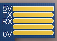 |
| PCB Connector for UART Debug |
Utilising the smallest component footprint in a product's design can, in some instances, lead to the repair of a Printed Circuit Assemblies (PCA) transitioning from an in-house repair process to an external repairer.
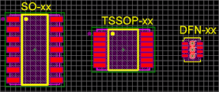 |
| SO, TSSOP and DFN Footprints |
 |
| BGA PCB Component |
For passive components, footprints such as 0402 and 0603 are a regular package size seen on a PCB design. Smaller package sizes such as 0201 and 01005 normally require additional equipment for board level component repair.
Component Solder Mask
For components with a pad to pad pitch 0.5 mm and smaller, including a solder mask between pads can be a challenging prospect.
The presence of a solder mask 'island' between component pads can be beneficial for service personnel performing rework and during visual inspection.
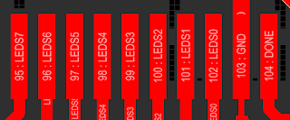 |
| PCB Extract Spirit Level U1 Top Layer. Courtesy Altium Ltd |
In the capture above the components pad to pad spacing of 0.5 mm was used with the default solder mask expansion of 0.1 mm which resulted in no solder mask between pads.
In the following capture, the default solder mask expansion layer was modified from 0.1 mm to 0.05 mm for the five pads on the right of the image.
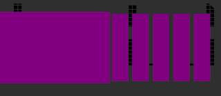 |
| PCB
Extract Spirit Level U1 Solder Mask - Modified. Courtesy Altium Ltd |
 |
| PCB Extract Spirit Level U1 in 3D with Solder Mask Modified. Courtesy Altium Ltd |
Connector Numbering Using Silk Screen
Numbering connector pins using a PCB overlay removes uncertainty and may well be a labour-saving for service personnel. Consider the capture of the connector below where pin numbering has not been provided on the silkscreen.
 |
| PCB Extract Spirit Level with Numbering Removed. Courtesy Altium Ltd |
The second capture, shown below with the original silkscreen, conveys the pins numbering legibly. For a densely populated board, free space on the silkscreen may not allow for numbering of individual pins. In these instances, a constant incrementing pin numbering pattern may still be beneficial for service personnel.
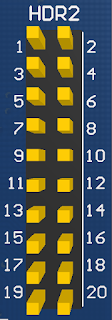 |
| PCB Extract Spirit Level with Original Numbering. Courtesy Altium Ltd |
Danger or Hazard Identification Using Silkscreen
A PCB silkscreen can be used to convey functional information relating to the PCB, product operation and any dangers service personnel may be presented with.
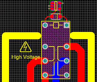 |
| High Voltage Identification Using PCB Silk Screen |
In the example design above, the silkscreen on the PCB provides details relating to the relay contact operating voltage.
PCB Test Point, Pad and Via
Adding the function of a test point to a components silkscreen was mentioned in the previous Design for Repair (DFR) post as a benefit for service personnel.
Other aspects of the test point which may need to be considered during PCB design include, fitting of a physical component, test point hole size, test point annular ring size or single-sided compared to a through-hole pad.
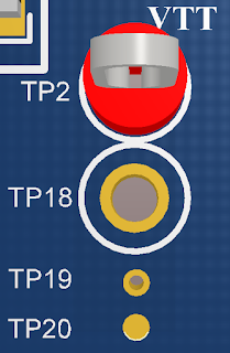 |
| Test Point, Via and Pad |
In the capture above, PCB mount Test Point TP2 is fitted to the board.
TP18 is the same component as TP2 and is not fitted to the board. With a sizeable diameter of 3.7 mm, this test point may not be suited for boards with a high component or routing density.
TP19 is a more common test point size. This features a 0.5 mm hole with a 0.8 mm annular ring. A hole of approximately 0.3 to 0.5 mm, without solder mask tenting, allows reliable connections with an oscilloscope or multimeter probes. Should there be a requirement, wires can be soldered to the thru-hole pad.
A major drawback with TP2, TP18 and TP19 is the area used by thru-hole parts which apply to all layers on the PCB.
One of the most common test point types shown in the capture is TP20. This test point is provided as a pad on a single side of the PCB. Pad diameters may range from 0.2 to 0.8 mm. Usually, this test point is used for In-Circuit Testing or programming boards. An important detail is the test pad wastes no real-estate under the pad compared to a thru-hole via. Wires can be soldered to the pad however it lacks the robustness of a thru-hole pad.
Surface Mount Nuts, Spacers and Standoffs
Disassembly and assembly of a product may constitute a significant portion of a products repair time if individual nuts, bolts, washers and stand-offs are used. Another option to minimise individual hardware items may be surface mount nuts or spacers.
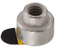 |
| M3
Self Clinching Nut (PEM) |
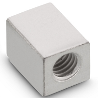 |
| SMT Right Angled Surface Mount Block. Courtesy Würth |
Final Thoughts
As each product design is unique, the examples in this blog should be drawn from a designers cache when applicable.
