Sunday 31 December 2023

Oscilloscope - Ringing on Waveform Measurements

Introduction
This post is an aide-mémoire for enthusiasts performing measurements using an oscilloscope on circuits that feature fast rise-fall times.

Oscilloscope Measurement Ringing

Background
While reviewing waveforms posted online for Time Domain Reflectometry (TDR) circuits, some waveforms appeared to have ringing that may be a result of excessive lead lengths used during oscilloscope measurements.

Measurements
In this post, the example the rising edge of waveforms were captured using test equipment consisting of a 300 MHz 2 GS digital oscilloscope, a passive probe (calibrated) and a PSoC5 LP for signal edge pulse generation. The PSoC5 output pin was clocked at 4 MHz with a rise time of over 10 ns
(Infineon-AN72382_Using_PSoC_3_and_PSoC_5LP_GPIO_Pins-ApplicationNotes-v09_00-EN.pdf, Greg Reynolds, Cypress, Rev H, 2018).

In the subsequent section, example 1 was the worst-case measurement for signal ringing and example 4 was an improved setup and measurement.

Example 1. Long Lead from Probe Tip and Long Earth Connection

Example 1 - Connections for Measurement

In this example, the cable lengths connected to the oscilloscope probe contribute mostly to the signal ringing. Other factors such as impedance mismatch were not reviewed as part of this post.

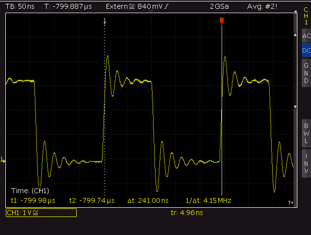
Example 1 - Oscilloscope Measurement

Example 2. Long Lead from Probe Tip and Leaded Oscilloscope Earth Connection

Example 2 - Connections for Measurement

Shorter cable lengths reduced the ringing however ringing was still prevalent.

Example 2 - Oscilloscope Measurement

Example 3. Direct Connection to Probe Tip and Leaded Oscilloscope Earth Connection

Example 3 - Connections for Measurement

This change to the connections was the largest improvement compared to examples 1 and 2. Ringing was improved with a direct probe connection and a shorter Earth lead although the return path through Earth lead could be reduced further.

Example 3 - Oscilloscope Measurement

Example 4. Direct Probe Tip and Ground Spring Connection

Example 4 - Connections for Measurement
 
A further improvement compared to example 3 with minimal lead lengths.

Example 4 - Oscilloscope Measurement

Example 5. Long Measurement Trace and Oscilloscope Earth Connection (Slow Edge Rate)

The capture below was made from the same hardware setup as example 1 and the PSoC was programmed for a slow instead of a fast edge rate.

Example 5 - Oscilloscope Measurement

Direct Connections
If a direct connection to a circuit board is possible, a board-mounted fixture in an option. These fixtures allow the oscilloscope probe tip to be inserted directly into the fixture. Some examples of fixtures for probing can be sourced from suppliers such as Teledyne, Cinch and Tektronix.

Example of Circuit Board Fixture (Courtesy Digikey)
Example of Circuit Board Fixture (Courtesy DigiKey)

Summary
Attention to measurement techniques can improve oscilloscope measurements however these are not always practical. While this post touches on one possible change that can be made to measurements, other factors should also be researched and considered depending on the type of signal. Further literature and content including passive probe compensation is available from manufacturers such as Teledyne. Detailed content for oscilloscope measurements can be found from Analog.

Tuesday 5 December 2023

Salvaging from a WAG120N Router

Introduction
This blog looks at salvaging parts and designs from a Linksys ADSL router model WAG120N.

WAG120N
WAG120N (Courtesy Google Images)

Parts Salvaging
Firstly flipping the router over to reveal the base of the unit, there are four plastic screws retaining the lid. After removing the screws, the lid can be detached from the base (two plastic shells) with a small flat-blade screwdriver or plastic prying tool.

Bottom View of WAG120N Router

Removing the lid shows the internals of the router; a circuit board and a dedicated antenna.

Internal View of WAG120N Router

Circuit Board - Top Side
The DC-DC Stepdown converter from ITE Tech part CAT7105CA (purple box in image below) is not listed as a part online; the status of the part is unknown. Not worth salvaging unless for a repair to a similar router.

Identified Parts of WAG120N Router Circuit Board - Top Side

The serial flash from Taiwanese manufacturer
Macronix International, part MX25L3206EMZI-12G (red box), is not large in capacity but could be salvaged. As with other parts, this part appears to be obsolete.

Capacitor manufacturers are Leylon and Luxon. These parts appear to be in good condition although for the age of the router, these may not be worth salvaging.

There are two through-hole crystals on the board, 25 MHz and 36 MHz (black box). Depending on needs, either crystal could be useful for small or hobby projects.

Under the small aluminium heatsink is the part responsible for the 802.11 communications, Ralink RT3050F (yellow box).

Other parts such as the memory (green box), ADSL controller (blue box) and the enclosed metal can device were not reviewed. The remaining items such as the LEDs could be easily salvaged.

Salvaging the mechanical items such as the switch, power jack, push button and connectors could be possible with the appropriate equipment.

Circuit Board - Bottom Side
The linear regulator used on the board appear to be manufactured by General Semiconductor which was acquired by Vishay Semiconductor some years ago. The part on the circuit board GS117A (red box in image below) appears to be obsolete although this is a jelly bean regulator.

Identified Parts of WAG120N Router Circuit Board - Bottom Side

Some parts with markings, NF B1386L, are possibly a Unisonic transistor 2SB1386L (blue box), not worth salvaging.

External and Circuit Board WiFi Antennas
The external antenna pictured below from Galtronics could not be located as a product on the Galtronics website. The antenna may have been a custom design for the Linksys router.

Galtronics Router Antenna
Galtronics External Router Antenna

The mechanical antenna may be an interesting part to experiment with. For the second WiFi antenna, this is designed into the circuit board as pictured below.

Circuit Board Antenna for Router

Both antennas could serve as reference design in the WiFi domain by providing dimensions or a circuit board layout.

Summary
In general, the physical parts from the Linksys router were not worth salvaging. However, the dedicated external WiFi antenna from Galtronics was an interesting hardware design.