Summary
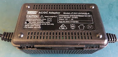
This blog details the repair of a JT-DC12C5A(II)-A switch-mode power supply.
 |
| JT-DC12C5A Power Supply |
Details
The switch mode power supply displayed above had been operating under high load for an extended period before failure. After failure, the DC 12 V output had reduced to less than DC 2 V.
Disassembly
Note: For repair to any AC 240 V equipment, due care and attention should be taken before undertaking service work or repairs. Unplug equipment before performing repairs!
Four plastic clips are integrated into the housing and one plastic screw hold the two-piece enclosure together.
After prying the case apart, the power supply circuit board was attached to the enclosure base plate.
 |
| JT-DC12C5A Circuit Board |
Servicing
A quick visual inspection of the board did not identify any burnt or charred sections on the PCB. The mains fuse continuity was good.
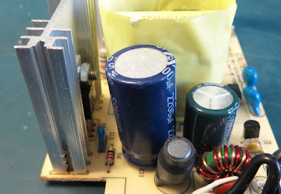
A slight bulge was noticed in one of the electrolytic capacitors located on the DC output stage. As shown in the image below, the top portion of the leftmost electrolytic capacitor is bowed upwards.
 |
| JT-DC12C5A Bulged Capacitor |
The suspect capacitor was unsoldered from the power supply PCB and checked with a capacitance meter. The measured capacitance was 1 nF where the capacity listed on the case was 470 uF.
 |
| JT-DC12C5A Replaced Capacitor |
A capacitor with a larger capacity of 2200 uF and the same working voltage was fitted to the circuit board.
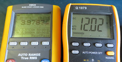
The unit was powered and a 2 A load was fitted to the output. Measuring the output voltage with the load was approximately DC 12.1 V.
 |
| JT-DC12C5A Output Load Test Measurements |
The unit was reassembled and another load test was conducted at around 4 A. Operation was verified by measuring the output voltage, approximately DC 12 V.
Summary
As far as power supply circuit boards repairs rate, this was uncomplicated. However, the change to the output capacitor was made to address possible ripple currents in the output that may have damaged the smaller capacitor. As always, the component specifications should be verified before replacing in any repair.


