This blog illustrates the impact of several heatsinking examples for surface mount resistors by using copper regions connected to the components pads. Connection of double sided copper regions, belonging to the same resistor, were achieved using thermal vias.
PCB
The material used in the example PCB was type KB6160A which is a standard FR4 1.6mm Tg of 135°C. Production of the example PCB was performed by manufacturer 3PCB (PCBWay).
Shown in the images below are captures of the top and bottom copper 'heat spreader' regions used on the board. For the heat source generation, nine resistors with a metric case size of 2010 were used.
To provide a point of reference, a control resistor (bottom left of image) was fitted with no spreader region. Eight other resistors, with varying sizes of spreader regions, were connected to the resistor pads.
Resistor Selection
A 750mW resistor with a 2010 case was selected after load testing a similar resistor in free air showed triple digit temperatures. The resistor selected was a 100R 750mW device from Vishay Intertechnology (Vishay), part number CRCW2010100RFKEF.
PCB
The material used in the example PCB was type KB6160A which is a standard FR4 1.6mm Tg of 135°C. Production of the example PCB was performed by manufacturer 3PCB (PCBWay).
Shown in the images below are captures of the top and bottom copper 'heat spreader' regions used on the board. For the heat source generation, nine resistors with a metric case size of 2010 were used.
To provide a point of reference, a control resistor (bottom left of image) was fitted with no spreader region. Eight other resistors, with varying sizes of spreader regions, were connected to the resistor pads.
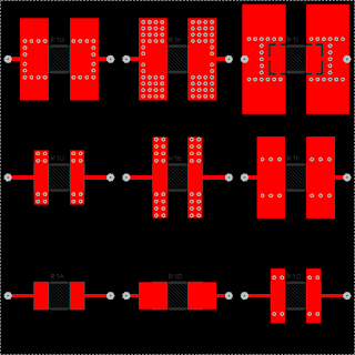 |
| Example Heatsink Board Top Copper |
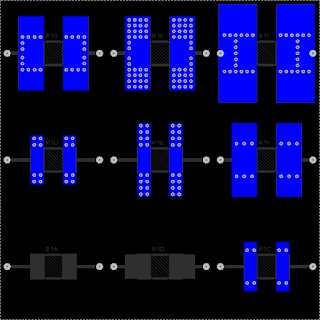 |
| Example Heatsink Board Bottom Copper |
Resistor Selection
A 750mW resistor with a 2010 case was selected after load testing a similar resistor in free air showed triple digit temperatures. The resistor selected was a 100R 750mW device from Vishay Intertechnology (Vishay), part number CRCW2010100RFKEF.
The resistor datasheet indicated derating for the resistor began at 70°C. Extracted from the datasheet is the derating graph below, all credits to Vishay.
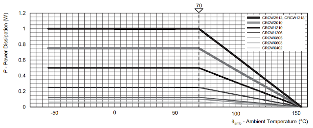 |
| Vishay CRCW Derating Graph |
Thermal Vias
While the spreader regions were designed into the PCB to illustrate the effectiveness of a small amount of copper for heat dissipation, the vias were used to thermally bridge the top and bottom copper regions. These vias were configured with a 0.5mm diameter and 0.3mm hole. The number of thermal vias were varied for some of resistors with the same size copper region.
One of the concepts for the example board, which was not implemented on the final prototype, was to provide an example of multiple vias with smaller holes. For the PCB manufacturer (3PCB), selecting vias with a hole size less than 0.3mm unaffordably increased the cost of the prototype by six times.
Resistor Testing
Temperature measurements were performed using a Flir C2 thermal imaging camera. A Rigol DP832 power supply provided half a watt (497mW) for each resistor tested.
Tests were conducted in a room with no airflow. The duration of each test was 30 min. After a brief period allowing for the PCB to cool down, testing was repeated. Thermal images were captured to highlight heating differences.
Testing Results
The table below shows the temperature measurements in degrees Celsius at the intervals listed.
Shown below is the graph of the measured temperatures.
Heat Spreader Region
Without a spreader region to dissipate heat, the control resistor (R1A) exhibited the largest increase in heating reaching a temperature in excess of 100°C. This temperature was used to reference against the other resistors tested.
As listed in the table above, resistor (R1I) had the lowest increase in temperature after 30 min of testing. This device also had the largest copper heat spreading region. The design of the spreader region for resistor R1I is rather impractical however due to the size however it served to illustrate that a significant increase in the area of the spreader region was required to achieve a similar characteristic as resistor R1H. The increase in copper spreader area between resistor R1I and R1H was over 220%.
With regards to the number of thermal vias used to stitch the spreader regions, the differences between resistors R1F to R1H should be closely noted. There were 12 vias used with resistor R1F, 24 vias R1G and 72 vias with R1H. The difference between temperature measurements for the resistors R1F to R1H was 75.2°C, 75.6°C and 73.8°C respectively.
Thermal Images
The images shown below were captured at various times during the testing process.
The thermal image for the reference resistor R1A shows localised heat only.
The thermal image for R1B, R1C and R1G are shown below.
In comparing the thermal images of the reference resistor R1A with resistors having increasingly larger copper heat spreader regions, the transfer of heat into the spreader regions is noticeable.
Resistor R1I was added to the board with the spreader regions connected with thermal reliefs. Although the spreader regions were larger, the transfer of heat was achieved using three 0.5mm tracks on each pad of the resistor. Only a single row of stitching was provided around the heat source.
Summary
The use of copper on PCB's to dissipate heat has been described in technical detail by several sites such as Texas Instruments, ON Semi and numerous blogs.
This blog provides thermal images showing the capability of copper spreader regions for heat dissipation. Furthermore the temperature measurements indicate that placement of vias in close proximity to the heat source, with reference to resistors R1F through R1H in this blog and not number of vias, is more critical for the transfer of heat.
While the spreader regions were designed into the PCB to illustrate the effectiveness of a small amount of copper for heat dissipation, the vias were used to thermally bridge the top and bottom copper regions. These vias were configured with a 0.5mm diameter and 0.3mm hole. The number of thermal vias were varied for some of resistors with the same size copper region.
One of the concepts for the example board, which was not implemented on the final prototype, was to provide an example of multiple vias with smaller holes. For the PCB manufacturer (3PCB), selecting vias with a hole size less than 0.3mm unaffordably increased the cost of the prototype by six times.
| Extract from 3PCB Online Quotation System |
Temperature measurements were performed using a Flir C2 thermal imaging camera. A Rigol DP832 power supply provided half a watt (497mW) for each resistor tested.
Tests were conducted in a room with no airflow. The duration of each test was 30 min. After a brief period allowing for the PCB to cool down, testing was repeated. Thermal images were captured to highlight heating differences.
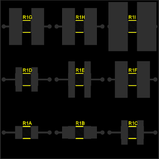 |
| Example Heatsink Board Top Silk |
The table below shows the temperature measurements in degrees Celsius at the intervals listed.
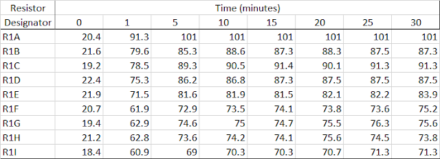 |
| Measured Temperatures for Example Heatsink Board |
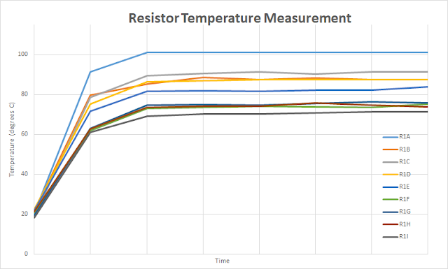 |
| Graphed Temperature Results for Example Heatsink Board |
Without a spreader region to dissipate heat, the control resistor (R1A) exhibited the largest increase in heating reaching a temperature in excess of 100°C. This temperature was used to reference against the other resistors tested.
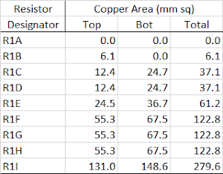 |
| Area of Copper Spreader Regions on Example Heatsink Board |
With regards to the number of thermal vias used to stitch the spreader regions, the differences between resistors R1F to R1H should be closely noted. There were 12 vias used with resistor R1F, 24 vias R1G and 72 vias with R1H. The difference between temperature measurements for the resistors R1F to R1H was 75.2°C, 75.6°C and 73.8°C respectively.
Thermal Images
The images shown below were captured at various times during the testing process.
The thermal image for the reference resistor R1A shows localised heat only.
 |
| Thermal Image of R1A on Example Heatsink Board |
 |
| Thermal Image of R1B on Example Heatsink Board |
 |
| Thermal Image of R1C on Example Heatsink Board |
 |
| Thermal Image of R1G on Example Heatsink Board |
 |
| Thermal Image of R1I on Example Heatsink Board |
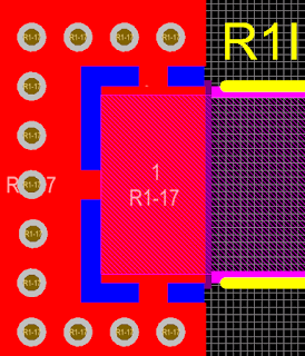 |
| Thermal Relief used with R1I on Example Heatsink Board |
The use of copper on PCB's to dissipate heat has been described in technical detail by several sites such as Texas Instruments, ON Semi and numerous blogs.
This blog provides thermal images showing the capability of copper spreader regions for heat dissipation. Furthermore the temperature measurements indicate that placement of vias in close proximity to the heat source, with reference to resistors R1F through R1H in this blog and not number of vias, is more critical for the transfer of heat.
