Introduction
This blog provides a teardown of the Risinglink PD201W Power Failure Detector and wall plug adaptor.
 |
| Risinglink Module |
Power Failure Detector Supplier
The power failure detector is branded with the logo of the company Risinglink. There are no product specifications for the detector on the Risinglink website but documentation is provided with the detector when purchased.
Package Contents
A mains wall plug (USA), USB cable and documentation are shipped with the power failure detector shipment.
Opening the Detector
A thin flat bladed screwdriver was used to release the lid from the case. The joint near the R and K in the Risinglink logo was the optimum lid leverage position. The plastic lid has two clips to retain the lid in the housing.
 |
| Risinglink Module Internal |
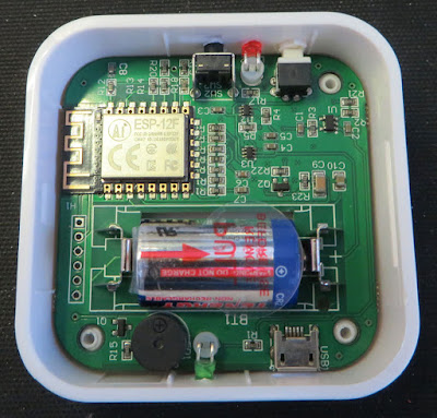
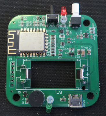
The ESP-12F WiFi module, CR2 battery, buzzer, switches and LEDs are immediately visible on the circuit board upon opening the unit. Removing the circuit board was possible by pressing the green LED away from the edge of the case. There are no components on the bottom side of the circuit board.
 |
| Risinglink Circuit Board |
The battery manufacturer’s website (Tenergy) shows that the battery cell has a capacity of 800 mAh (Lithium).
According to the ESP datasheet, operating the WiFi at continuous transmission draws an average of 71 mA. This would theoretically mean that a fully charged battery could monitor the status of the mains for hours.
As detailed in the documentation shipped with the detector, the white switch powers the detector with visual feedback provided by the red LED.
The black pushbutton is used to change operating modes as required when configuring the detector.
For the USB connector, only the power connections are utilised for monitoring the mains. No USB communication is possible to the detector. USB power is indicated through the illumination of the green LED.
Email Details
Notification emails are sent with “via amazonses.com” in the address. Emails events are received on the initial start-up, when a power outage occurs or when power restoration is detected.
The device PowerDetector started. Below is the device status at 01/01/2023 12:00PM.
- Power Status: ON
- Battery: 100%
- WiFi Signal: -51
As mentioned in the documentation, an email is sent after 24 hours if there is no communication with the module.
The device, ............, may be OFFLINE. No ping from the device within 24 hours.
Please check WiFi connection, Internet service, etc. Please contact support@...... if any question.
Wall Plug
The wall plug (model HNT-H510) features an internal On-Bright controller responsible for the control aspect of generating DC 5V in either Constant Voltage (CV) or Constant Current (CC) mode. As the image from the wall below shows, the design is the usual compact solution.
 |
| Wall Plug Internals |
ESP-12F
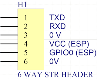
On the detector circuit board is an unpopulated 6-pin straight header (H1). Using the datasheet of the ESP-12F and a multimeter, the pinouts of the header were determined as displayed in the image below.
 |
| Pinouts for Risinglink Connector |
A TTL to USB converter was connected to the header pins Tx, Rx and 0 V. An oscilloscope was used to measure the transmitted UART data bit time which was approximately 13.3 ms or 75 bps during bootup. Data was shown however this was not reviewed in further detail. Programming information for the ESP can be found on dozens of sites, on example here.
Example data on boot.
ets Jan 8 2013,rst cause:4, boot mode:(3,7)
wdt reset
load 0x40100000, len 30596, room 16
tail 4
chksum 0x3e
load 0x3ffe8000, len 2004, room 4
tail 0
chksum 0xa1
load 0x3ffe87e0, len 4752, room 8
tail 8
chksum 0x6a
csum 0x6a
Modifying the Power LED
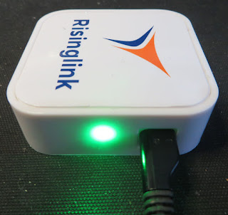
Situated on the side of the detector housing is a green LED. When a 5 VDC USB power adaptor is connected, the green LED bursts into operation. The brightness of the LED may be beneficial for a large factory but for a confined space, the LED brightness may benefit from a reduction.
 |
| Bright LED on Risinglink Unit |
The green LED uses a 1 k 0603 current limit resistor, R1.
 |
| Resistor R1 on Risinglink Unit |
To reduce the brightness of the LED, resistor R1 was increased to 10 k with the effects shown below. Resistor R1 was located between the green LED and the USB connector as shown in the capture above.
 |
| Dimmer LED on Risinglink Unit |
Final Thoughts
The Risinglink PD201W is reasonably designed and simple to use. An option to use a custom email client over Amazon services would be preferable, especially for clients needing to security harden their network.
Additionally, a helpful upgrade to the detector could be a battery-only access panel or a rechargeable battery.
