Saturday 1 December 2018

Isolation Transformer Build Medical Grade 240V

Summary
This blog details the build process of an enclosure for isolation transformer using a medical grade toroidal transformer.

Medical Grade Transformer
There are significant benefits in using a medical grade toroidal transformer over a standard type. These include multiple layers of winding insulation, reduced leakage currents and certain types of internal transformer failures can lead to a winding short to mains earth resulting in protected equipment and operators. Such a short to mains earth is achieved because a medical transformer contains a dedicated mains earth connection. Medical transformers are usually made to a international standard such as IEC / UL 60601-1.

Transformer Selection
A transformer manufactured by Triad Magnetics (China) was selected for mains 240VAC. The Triad Magnetics parts VPM240-670 is rated at 160VA which is usually ample for fault finding equipment or powering small pieces of test equipment. 


Triad Magnetics VPM240-670
The transformer features a number of winding options for 110VAC or 240VAC.

Triad Magnetics VPM240-670 Side View
For this design the primary and secondary will be configured for 240VAC operation.

Hardware Selection
In addition to the transformer are a number of key components such as the enclosure, IEC connectors, fuses and switch. A standard plastic enclosure was chosen to house the transformer as the expected operational time was low. For long operating periods a vented case would be used.


Enclosure
Enclosure
Shown below are the fuse holders and IEC inlet outlet chassis mount connectors.


Associated Isolation Transformer Hardware
Hardware Mounting
The hardware required for the design was measured and the mark-ups were made on opposite ends of the enclosure.


Inlet and Fuse holder Mounting
Outlet and Fuse holder Mounting
Standalone 3AG fuse holders were chosen over IEC connectors with integrated M205 type fuses however either is suitable for this design.


Transformer Mounting
Mounting for a double pole rocker switch and the transformer were added.

Hardware Dry Fit
Each piece of hardware was mounted to ensure that fitting was suitable and clearances were sufficient.


Hardware Dry Run
Hardware Dry Run
Enclosure Wiring
Salvaged mains 300V AC rated cable was used to wire between the IEC connectors and the fuses.


300V Mains Cables
300V Mains Cables
All mains connections were soldered and the mains wire was passed through the eyelet as shown below.


IEC Mains Cable Connection
All connections were insulated with heat shrink tube.


Fuse with Heatshrink
Fuse with Heat shrink
 
The image below shows the rather snug wiring prior to testing. Additionally, while tightening the IEC fixings the case cracked meaning the entire case would need to be replaced after some initial testing.


Wired Isolation Transformer
Regulation Testing
The transformer was wired for 240V AC on the primary and secondary.


Transformer Input and Output Options
 
Shown in the image below are the transformer windings as detailed on the Triad Magnetics datasheet.
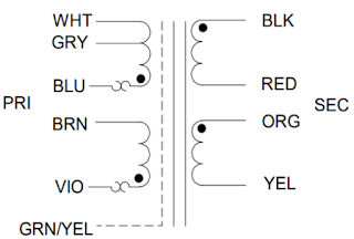
Transformer Windings
Using the wiring configuration for 240VAC, regulation measurements were performed to approximately 130VA using a Fluke 325.


Triad Magnetics Transformer Regulation
 
With a load of 130VA the transformer regulation was approaching the 7.2% maximum quoted regulation of the transformer at full load.

Comments 
With very small loads the transformer secondary voltage is almost 10% higher than the primary voltage. For voltage sensitive equipment this differential may be a limiting factor although for standard bench testing this transformer is more than suitable.

Thursday 22 November 2018

Salvaging electronic parts - Part 3 BenQ GL2430 Monitor

Summary
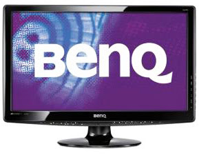
This blog continues a series of salvaging electronic parts, this time focusing on a BenQ model GL2430 monitor and what components could be salvaged. 


GL2430-B  BenQ Monitor
GL2430-B  BenQ Monitor
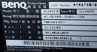
The monitor build date was from early 2011.


GL2430 Name Plate
GL2430 Name Plate

Salvaging
The dismantling process for the monitor was skipped. The two major and two smaller printed circuit boards (PCB) removed from the monitor were: Flat panel driver board, Power supply board, Backlight driver board and Audio breakout board.

Flat panel driver board
Shown below is the flat panel driver board, single sided multilayer circuit board. This board contains the Realtek flat panel driver IC boxed in blue. Realtek part RTD2483RD. 


GL2430 Flat Panel Driver Board Top Side
Boxed in red of the image are a mixture of five serial memory devices ranging from ST Micro 24C02 EEPROM to a Winbond 2Mbit Flash W25X20. These devices are usually very easy to salvage.

Boxed in yellow are some of the numerous inductors on the board.

The semiconductor in the top right hand corner of the image is a Diodes Inc PAM8603 - 3W stereo class D amplifier. Possibly not worth salvaging as there are parts available with lower distortion ratings.

In the bottom left hand corner of the board are a pair of TVS arrays from the manufacturer InPaq 1045QU. Again probably not worth salvaging.

The crystal on the board is common video 14.318MHz type and could be repurposed if any crystal frequency is suitable.

Remaining on the board are a mixture of connectors, passives and unidentified semiconductors. If you were really scratching to find a MELF diode or 220uF Lelon Electrolytic then this board could be added to the spare parts box.

Power supply driver board
The power supply board is populated with components on both sides, double sided with a single layer PCB design. Heavy through hole components on the top side of the PCB and smattering of glued surface mount components on the solder side.


GL2430 Power Supply Board Top Side
Boxed in red is the mains common mode choke and towards the centre of the board, the switching transformer. Both these devices are manufactured by a Taiwanese transformer manufacturer. These parts can come in handy for research and design projects and a worth salvaging.

The green boxes highlight a few resistors which could be extracted for the spares bin. There are no signs of overheating or other physical damage which may have been caused by a fault on the PCB.

In the blue boxes are the diodes and bridge rectifiers. The bridge rectifier is listed as an obsolete part on supplier's websites such as Mouser so may be good for the spare parts box. The two larger axial diodes are Vishay part UG4B; a reputable brand worth salvaging once properly tested.

The two devices on heatsinks are the mains side switching MOSFET K4101 and secondary side dual rectifier diode FMX12S. At least one of these devices has discolouration in the PCB surrounding the heatsink. Heatsinks could be salvaged for other purposes.

Remaining on the top side of the board are various connectors, mains voltage rated varistors and mixture of capacitors. Usually components which have been operating at mains voltages for an unknown amount of time can left on the PCB if the operational state of these parts is unknown.


GL2430 Power Supply Board Bottom Side
Shown above is the solder side of the power supply board. To the left of the image is the switch mode controller. Across the board are a number of other parts, all glued down with epoxy. Using epoxy to glue surface mount components in order to simplify the assembly process is standard practice. The epoxy can make repair and salvaging parts difficult.

Backlight driver board
Below is an image of the backlight driver board. The main LED driver, boxed in red, is an MP3389 from Monolithic Power. Device is worth salvaging or even the entire board itself as it is a self-contained unit which could easily be reused.


GL2430 Backlight Board Top Side
Boxed in blue is an unbranded inductor which is always good to have in the spares box.

Shown in the yellow box is a SinoPower MOSFET APM1110 which was not located on the company website. Specifications are nothing to be excited over although part would be worth salvaging for prototyping.

The remaining passives such as the radial capacitors are from Lelon making the remainder of the board a contender for the spares box.

Audio Connector board
Lastly is the small 3.5mm audio connector board. The connectors are a standard pinout and could be salvaged or the entire board repurposed for a bespoke project.


GL2430 Audio Connector Board Top Side

Design Notes
A section of the power supply mains input section was chosen for some brief notes on PCB design.


GL2430 Power Supply Board Main Input Section
Boxed in white, top left hand corner of the above image, is the one of the mounting holes with exposed long pads coated in solder. This is a good feature for eliminating star or copper washers however the electrical resistivity can suffer due to the smaller contact area and surface oxidisation of the solder. It should be noted that on the component side of the board is a through hole nut allowing direct access to the mains earth connection.

In the orange boxes are several slots on the board to improve the creep distance between component pins. Slots in the board are an effective and cheaper solution to conformal coating.

Shown in the blue box is attention to detail by the PCB designer. A small pullback was applied to the copper surrounding the two mounting holes for the IEC mains connector.

Boxed in purple is a section of silk screen showing the isolation plane between mains AC and isolated DC voltages. The silk screen for the isolation plane and most components is present on both sides of the PCB making component identification and servicing easier.

Lastly the red box shows three cascaded surface mount resistors used in series to discharge the mains input capacitor connected between active and neutral. The PCB designer was mindful of creep distance and to some degree spacing between these components.

Saturday 13 October 2018

Rigol DP832 Output Capacitor Limitations

Summary
This blog details a hindrance with the Rigol DP832 power supply outputs when used for purposes such as characterising digital inputs, circuit reaction times or external power supply transient performance to name handful.


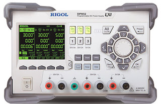
Rigol DP832
Rigol DP832

DP832 'Gotcha'
The Rigol DP832 is a good mid-range power supply sporting an easy to use interface to suit the hobbyist and options such as remote communications and power cycling to cater for some professional applications. For engineers familiar with power supply interruption testing, as defined in EN61496-1, the Rigol DP832 can be setup, with some fiddling, to assist with compliance tests.

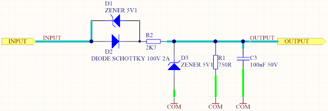
It was the power cycling feature on the DP832 that was to be used for testing the PLC input design, however after the first few power cycles some unexpected measurements were observed. The configurable PLC input section circuit is shown below.


PLC Input Section
PLC Input Section

The power On captures shown below illustrate the difference between using the Rigol On/Off power button and the second capture shown the response using an external switch with the Rigol power button set to On.


Power ON Delay using Rigol Power Button

Power ON Delay using External Switch - Rigol Power ON

The delay in powering the circuit Off was also easily visible on the scope.


Power OFF Delay using Rigol Power Button

Power OFF Delay using External Switch - Rigol Power ON

Output Capacitance
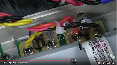
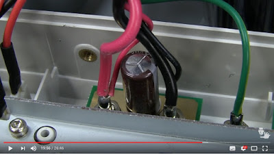
Looking at the captures from the scope this appeared to be output capacitance. I recalled that Dave Jones from EEVBlog had torn down the DP832 several years ago; the output capacitors where found in EEVBlog #511; credit and many thanks to Dave Jones saving me the teardown.

The output capacitors appeared to be 1000uF electrolytics, which would explain the delayed switching performance.


EEVBlog #511 DP832 Output Capacitors - 2 Channels

EEVBlog #511 DP832 Output Capacitors - 1 Channel

Output Solution
As a temporary solution to testing, a relay was added. Channel one performed the relay coil switching and Channel two was left powered with the output connected to a Normally Open relay contact. The switching response was did not have the effect of the capacitor charge time although some relay contact bounce was evident.

Saturday 6 October 2018

Asus X202E Restoring Windows 8.1

Summary
This blog details the rather simple restoration process of Windows 8.1 on an Asus X202E which previously had Lubuntu installed. The motive was rather benign; a terminal application capable of supporting 921600 baud with a logging capability, such as RealTerm or TeraTermwas required.

The Asus X202E was factory shipped with the Windows keys in the netbook 'hardware' meaning Windows 8.1 could be restored under the provision that the installation media could be downloaded.

Downloading Windows 8.1
Before proceeding down the rabbit hole that is Windows, a search for the Windows installation media was made. To my amazement the ISO was available from Microsoft - https://www.microsoft.com/en-au/software-download/windows8ISO

Installation Media
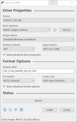
To create the installation (USB) drive Rufus 3.3 was used. Rufus, by Pete Batard / Akeo, is one of the 'go to' applications for boot drive creation under Windows.


Rufus 3.3 - Windows 8.1 Boot Drive Creation
The capture above shows the default settings used to copy the Windows 8.1 ISO onto a 16 Gb bootable thumb drive.


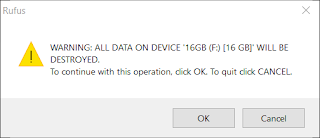
Rufus 3.3 - Overwrite Thumb Drive
After confirming the drive can be overwritten the process was run until completion.

Asus X202E BIOS
With the Windows USB boot drive installed in the Asus X202E and the power off, the BIOS was activated. For this model X202E, the F2 key was held then the power button pressed. The F2 key was only released when the BIOS was displayed. See the Asus website FAQ for further details.

In the Boot menu the USB drive was selected.


Asus X202E - USB Boot Option
The change to the boot was then saved and the Asus allowed to restart.

Standard Windows Installation
Subsequent to the Windows USB drive starting the usual installation process is followed.
Asus X202E - Windows Installation Splash
The standard Windows agreement screen and setup options.

Asus X202E - Windows Agreement
Followed by the Windows installation screen.


Asus X202E - Installation Screen
After the Asus restarted the Windows setup completed without any issue.

Thursday 6 September 2018

Surface Pro (2018) for Embedded Software Development

Summary
This blog examines the feasibility of using the Surface Pro 2018 'Surface' as an alternative to a Windows based laptop or desktop machine for the purpose of embedded software development.

Consideration was given to targeted metrics which consisted of physical handling, connectivity, storage speed and keyboard solutions. For a performance comparison, two common software packages were used to compile example projects on the Surface and a reference Asus laptop. Metrics dependent on factors which were difficult to verify, such as battery life, were not examined.


Surface Pro i5
Surface Pro i5
Testing was performed on a Surface Pro i5 over the duration four weeks, with the default Windows 10 Professional installation.


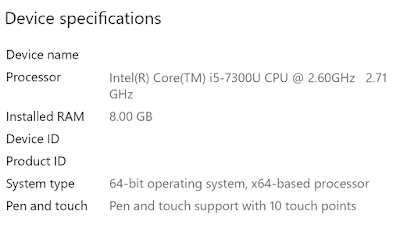
Surface Pro Hardware

The Surface Pro i5 uses the Intel 7300U processor and was loaded with 8GB of RAM running Windows 10 Professional.


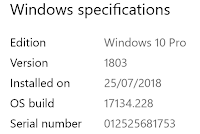
Surface Pro Windows Version

Handling and Portability
As a desktop replacement, without the addition of a keyboard such as the Surface Type, the Surface Pro 'Surface' is a befitting of the name space saver. Notably for small benches or work spaces the footprint of the Surface is very appealing which makes shifting or repositioning the Surface comparably easy moving from a laptop.

Off the bench in general use, the low weight of the Surface results in relative ease of movement. The kickstand was adjusted in the same manner a laptop display would be moved to cater for varying locations or seated positions.


Bluetooth
During point and select operation during code changes, use the Surface Pen was used without any issue. Other Bluetooth devices in the same proximity to the Surface did not cause any interference. 

Wireless
The wireless maintained connection whether at short distances (1m) or longer distances (30m) from a wireless router (BiPac). Only one dropout was noted during the test period.

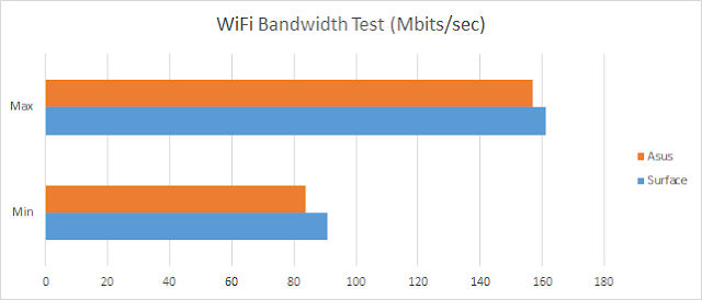
Wi-Fi Bandwidth testing was performed using a local server, albeit slow. The Surface and Asus devices were both loaded with IPerf 3.1.3, then several tests conducted. Tests were conducted using the bidirectional configuration in IPerf.

SO_SNDBUF is 212992
[  4] local x.x.x.x port 56795 connected to y.y.y.y port 5201
[ ID] Interval           Transfer     Bandwidth
[  4]   0.00-1.00   sec  18.8 MBytes   157 Mbits/sec
[  4]   1.00-2.00   sec  15.8 MBytes   132 Mbits/sec
[  4]   2.00-3.00   sec  12.8 MBytes   107 Mbits/sec
[  4]   3.00-4.00   sec  11.5 MBytes  96.2 Mbits/sec
[  4]   4.00-5.00   sec  10.8 MBytes  90.4 Mbits/sec
[  4]   5.00-6.00   sec  10.0 MBytes  83.7 Mbits/sec
[  4]   6.00-7.00   sec  11.6 MBytes  97.6 Mbits/sec
[  4]   7.00-8.00   sec  11.0 MBytes  92.3 Mbits/sec

[  4]   8.00-9.00   sec  10.8 MBytes  90.1 Mbits/sec

Shown below are the results of the bandwidth tests conducted.


Surface Pro vs Asus Wi-Fi Bandwidth Results
USB
The Surface's single port USB connection could certainly be considered a limitation for a embedded software or hardware developer who may need two or more USB ports.

During development the single Surface USB port was connected to a USB hub which facilitated a mouse, keyboard and programming adaptor. In some instances a serial adaptor was required. There were no issues relating to the download of drivers, operation of the USB or the performance of the adaptors.


Storage
For copying medium sized (>500Mb) files between computers either, an SD card or USB drive was used. With a meagre 128 Gb internal SSD, the removable SD card was used to store working files and backups.

The USB port was usually broken out to a hub, consequently little commentary on use with insertion of various USB equipment.

Inserting and removing the SD card from the Surface was seamless. The location of the SD slot behind the kickstand resonated with me for typical operation. 

For comparison of copy speeds for the SD card, an Asus i7-77HQ provided results as a reference device.

SD Speed
SD Card testing was performed with a Strontium Nitro 433X Class 10 16 Gb SD using the test software H2testw 1.4. This package was selected because it was capable of testing SD and USB.


Strontium Nitro 433X
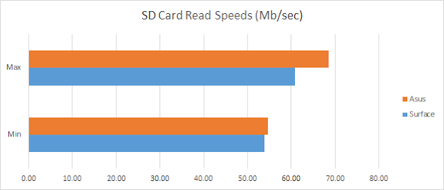
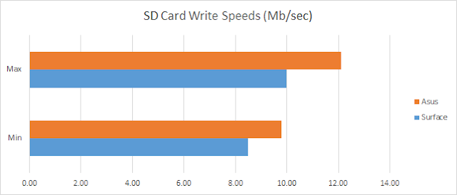
Several tests were conducted using the Strontium Nitro on the Surface and Asus with the results displayed below.


Surface Pro vs Asus SD Card Read Speeds


Surface Pro vs Asus SD Card Write Speeds
USB Speed
Speed testing was performed with a Silicon Power USB 3 32GB drive using the same test software, H2testw 1.4, that was used with the SD card.


Silicon Power USB 3 Drive
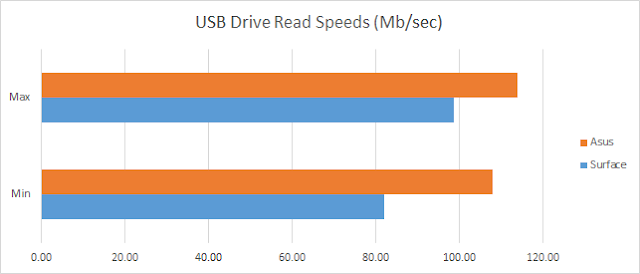
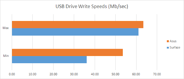
Again several tests were conducted using the Silicon Power USB on the Surface and Asus with the results displayed below.


Surface Pro vs Asus USB Drive Read Speeds
Surface Pro vs Asus USB Drive Write Speeds
Software Compile Times
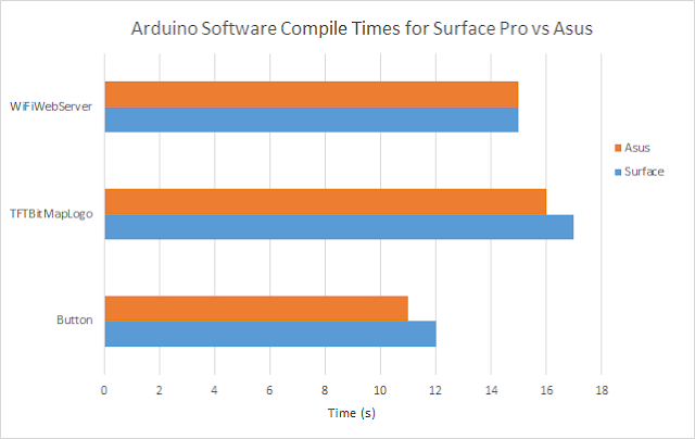
The first application used for comparing software compile times was the 'Maker' popular Arduino, version 1.8.6.

Arduino
Three example projects were built on the Surface and an Asus laptop. Timing of the compile process was performed manually therefore some tolerance in timing shall be noted.


Surface Pro vs Asus Arduino Project Compile Times
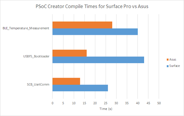
PSoC Creator
Again three example projects provided by Cypress were built on the Surface and an Asus laptop using PSoC Creator 4.2 'IDE'. Timing of the compile process was taken from the start and end times noted in the IDE output window.


Surface Pro vs Asus PSoC Creator Project Compile Times
Code Editing
Editing code with an application such as PSoC Creator, utilising the on-screen Surface keyboard was more cumbersome compared to a standard mechanical keyboard. One of the primary reasons was the standard Surface keyboard on-screen layout results in additional key presses to realise straightforward characters. For instance, at worst case, curly, round or square brackets would require three button presses.
A further reason for using a Surface Keyboard or a similar external keyboard solution was the on-screen keyboard does not display when text areas are clicked for editing. The on-screen keyboard had to be invoked manually.


Silicon Labs PSoC Creator Project on Surface Pro
On-Screen Keyboard
There were some initial complications with phantom presses. Applying the Microsoft HotFix for Surface Pro 4 resolved this issue.

Using the Surface Pro in landscape mode was personally the preferred option when writing code because the rear stand was used in the lowest position. Typing with the Surface flat on the desk was achievable although did not suit my office layout. The above image shows typically the ratio of code to keyboard that was used while developing the Silicon Labs blog.

Surface Pen
For specific editing tasks such as selection of text, repositioning selected text or moving on-screen objects the Surface Pen is a handy tool however, a standard external mouse will achieve the same result. People using the Surface Pen for more advanced tasks may have different feedback on its suitability.

Microsoft Surface Cover (Keyboard)
As a keyboard solution, the Surface Cover was more than reasonable with the depth of keystrokes sufficient to provide tactile feedback. The backlight keys on the Surface Cover were handy when typing whilst in low lighting conditions.


Surface Pro with Surface Cover
Final Thoughts
For embedded software development the Surface Pro is a worthy competitor to devices with similar specifications and features already in the market. 

In this setting, pro's for the Surface were the lightweight, fan less design, ease in handling and a solid Wi-Fi performance.

Unsurprisingly con's for the Surface related to limited connectivity resulting from the single USB port, throttled processor performance and initial phantom touch screen issues. The latter touch issue being the most obstructive as this phenomenon prevented device useability to the point of preventing logging onto the Operating System.

In a nutshell choosing the most suitable device ultimately depends on the requirements of the end user. Certainly for embedded software development other devices such as the middle to high end Lenovo Yoga, Dell Inspiron 13 or the HP Spectre may be a more suitable solution.