Introduction
This blog measures the voltage and timing differences
during simultaneous control of dual output high-side electronic drivers.
 |
| Parallel Dual High-Side Driver Test PCB |
Test Device
The electronic component discussed in this blog is the IPS2050H. This device is manufactured by ST Micro. The device is a dual output high-side driver with an operating voltage of DC 8 – 60 V with a current capability of either 2.4 A or 5.6 A.
This ST driver was originally considered for the Interruption Tester project which is detailed in another series of posts. Paralleling the outputs of the IPS2050H for a higher current remained a matter of interest however several characteristics of these devices are not listed in the datasheet. Information such as the difference between channel ON/OFF control voltages or switching times was seen as beneficial.
Paralleling Outputs
Literature on the subject of balancing currents when paralleling discrete MOSFETs
is widely available. One such paper, “Paralleling of Power MOSFETs for HigherPower Output”, by James B. Forsythe of International Rectifier, provides a
well-documented explanation of effects and techniques to normalise current
sharing between MOSFET devices. In this post, some of the points listed in the
International Rectifier paper were discussed and applied to the IPS2050H.
For further reading, Texas Instruments has a similar document "High Side Switches Paralleling Channels"
In a document with similar content, Infineon published an application note showing realistic gate voltage for high current applications "Paralleling MOSFETs in high-current LV drive applications"
Discussion
For those readers looking for an immediate answer to paralleling outputs of high-side drivers with multiple outputs, it is possible however the operation depends on the requirements of the load and driver.
The International Rectifier paper for MOSFETs was used as a guideline to review some aspects of the IPS2050H. Items from Section IV (c) Summary of Recommendations for Balancing Parallel MOSFET Currents were applied where possible.
Manufacturing of the IPS2050H would likely be performed on a single silicon wafer however there is commonly variation in characteristics across the wafer. Screening and parameter matching for the IPS2050H are not practical however, measurements were performed to determine differences between the devices two channels.
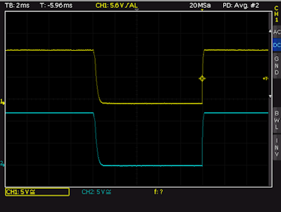
Parameter differences between channels were noted for Vin (ON) and (OFF).
 |
| IPS2050H Measured ON-OFF Voltages |
The delays between input and output switching were measured at room temperature, approximately 1.96 us for both channels.
 |
| IPS2050H Input to Output Switching Delay (No Load) |
The measurement for the switching delay was performed based on the
50 % input voltage and 10 % output voltage for the propagation delay as shown in Figure 3 of the IPS2050H datasheet.
 |
| Figure 3 Timing from IPS2050 Datasheet (Courtesy ST Micro) |
When switching the input of both channels ON simultaneously, without a load connected to either, the turn ON delay between channels was approximately 400 ns.
 |
| IPS2050H Turn-ON Delay between Outputs |
Next, a load consisting of a 10 R wire wound resistor was added to each channel. The turn-ON delay with the resistor was 17 us for one channel and 18 us for the other. The turn-OFF delay with the wire wound resistor was slightly over 7 us for both channels.
 |
| IPS2050H Channel 1 Turn-ON Delay with Wire Wound Resistor |
 |
| IPS2050H Channel 2 Turn-ON Delay with Wire Wound Resistor |
The output turn-ON delay between channel 1 and 2 with separate wire wound resistors was slightly over 25 us for both channels.
 |
| IPS2050H Channel 1 to 2 Output Turn-ON Delay with Wire Wound Resistors |
The output turn-OFF delay between channel 1 and 2 with separate wire wound resistors was again slightly over 7 us for both channels.
 |
| IPS2050H Channel 1 to 2 Output Turn-OFF Delay with Wire Wound Resistors |
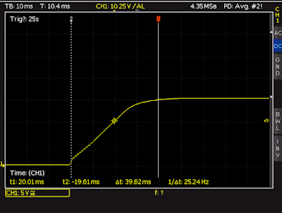
A capacitive load of 6800 uf was driven with various output configurations. For the first test, the two outputs were connected in parallel and wired to the capacitor. The charging waveform is shown below.
 |
| IPS2050H Parallel Channel 1 to 2 Capacitor Charging |
For the subsequent test, the two outputs each had a 3.3 R current sharing resistor fitted before terminating at the capacitor. As expected the capacitor charge time constant increased because of the introduced resistance.
 |
| IPS2050H Parallel Channel 1 to 2 Capacitor Charging through 3.3 R Resistors |
In the last configuration, two Schottky diodes were fitted to replace the resistors on each output before connecting to the capacitor.
 |
| IPS2050H Parallel Channel 1 to 2 Capacitor Charging through Schottky Diodes |
The time to charge the capacitor with Schottky diodes was approximately the same as the directly connected paralleled outputs. Note the lower voltage across the capacitor with the diodes due to forward voltage losses.
Each channel of the IPS2050H driver was individually loaded to 1.5 A and the voltage across separate wire wound resistors was measured with both inputs of the device ON. The output voltage at channel 1 measured 15.051 V and channel 2 measured 15.089 V.
The IPS2050H inputs were driven using a square wave with a 90 % duty cycle. The output voltage at channel 1 measured 14.968 V and channel 2 measured 15.015 V.
 | |
|
PCB Traces
As stated in the paper by International Rectifier, the addition of series resistance would not be required for a design with MOSFETs. The traces on the test PCB outputs were duplicated as shown in the image below.
 |
| Highlighted Output Polygon Traces on Top Layer of Test PCB |
Common source inductance was not reviewed in this post. Since the MOSFET gates are not accessible, drive modifications were not possible. The decoupling resistance (gate resistor) would likely be part of the control circuit block in the IPS2050H, as shown in the capture below, therefore this was also not investigated.
 |
| IPS2050H Functional Block Datasheet (Courtesy ST Micro) |
Final Thoughts
Measurements performed on the IPS2050H indicated there are minor difference in turn ON/OFF threshold voltages and switching delays. These timing differences may result in one channel of the IPS2050H momentarily handling most of the switching energy at on turn ON and then at turn OFF. This time difference was measured in microseconds for the loads tested, which may be acceptable time for some designs but a hindrance for other designs where high instantaneous currents are required.
For a more comprehensive review, current measurements from each of the parallel outputs in a target circuit would provide clarity on the demand placed on each driver output. Temperature measurements could also prove beneficial to ensure that the device’s maximum operating specifications were not exceeded.
