Summary
This blog details the second stage retrofit of a Rexon RDM150D drill press. The second stage added movement monitoring of the spindle and a requirement to deactivate the drill press run switch after triggering the ESTOP. The first stage retrofit blog contained details relating to controller design and the drill press wiring.
Electrical Wiring - Stage 1
The first stage changes to the drill press electrical, which included the ESTOP button and controller, are shown in the image below.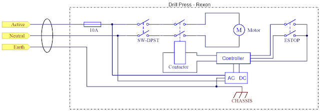 |
| Rexon RDM150D Stage 1 Electrical |
Electrical Wiring - Stage 2
For the second stage retrofit, a proximity switch and a relay were added to the design. Both the new devices were connected to the controller.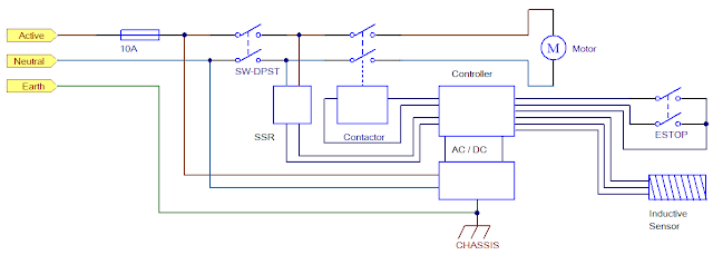 |
| Rexon RDM150D Stage 2 Electrical |
For detection of rotational movement in the pulley responsible for driving the spindle, an inductive sensor was selected.
 |
| MCPIP-T12L-001 Courtesy Multicomp |
The sensor was manufactured by Multicomp, part MCPIP-T12L-001, which features a PNP output, M12 thread and a 2mm sensing distance.
DIN Relay
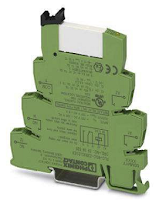
A relay was added to detect when the manual switch (DPDT) was in the ON state. Providing the manual switch state to the controller served two purposes, firstly the controller could determine when the spindle was active and secondly the same feedback signal could be used to ensure that the manual switch was OFF before the contactor was reactivated.
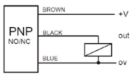 |
| Inductive Sensor PNP Electrical Connections |
A relay was added to detect when the manual switch (DPDT) was in the ON state. Providing the manual switch state to the controller served two purposes, firstly the controller could determine when the spindle was active and secondly the same feedback signal could be used to ensure that the manual switch was OFF before the contactor was reactivated.
The relay used was a DIN style, 240V input, from Phoenix Contact.
As shown in the second stage electrical drawing above, the input to the relay was driven from the equipment side of the manual ON OFF switch. The pair of secondary side relay Normally Open connections were individually connected to 24V and the Spindle Active input of the controller.
Sensor Hardware and Mounting
An oversight with the Multicomp sensor installation was the devices body length which prevented the sensor being mounted between two pulleys.
To mount the sensor inside the top housing of the drill press, a repurposed wall bracket was drilled to the required hole size (M12). Loctite 243 was used on the sensor thread. The bracket was fitted at an angle as shown in the above image. This prevented use of the lowest belt position between the spindle and middle pulleys. A shorter sensor, placed parallel to the belts, would be recommended for those implementing this design.
Triggering the sensor was achieved using a small steel angle fitted to the pulley. For a speed of 3000 RPM, best results were achieved when the length of the steel angle was 20 mm. Two M3 bolts with Loctite 243 and internal star washers were used to fix the steel bracket in position.
| Sensor Mounting Bracket |
Triggering the sensor was achieved using a small steel angle fitted to the pulley. For a speed of 3000 RPM, best results were achieved when the length of the steel angle was 20 mm. Two M3 bolts with Loctite 243 and internal star washers were used to fix the steel bracket in position.
| Sensor Steel Pulley Bracket |
Sensor Test Measurement
With the Multicomp sensor powered and an Oscilloscope fitted to the Out connection, one measurement was taken at a slow RPM and the second measurement at the fastest RPM.
 |
| Slow RPM Sensor Measurement |
 |
| Fast RPM Sensor Measurement |
Relay Mounting
The DIN relay was mounted between the contactor and the controller, as pictured below.
| Electrical Enclosure DIN Relay Mounting |
PSoC Inputs
The spindle and spindle active inputs to the PSoC controller were provisioned in the first stage controller design. Connections were made according to the updated inputs detailed in the section below.
Controller Wiring
A correction was required to the controller PCB overlay. The capture below shows the updated overlay reflecting the controller connections.
The spindle and spindle active inputs to the PSoC controller were provisioned in the first stage controller design. Connections were made according to the updated inputs detailed in the section below.
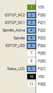 |
| PSoC Inductive Spindle Input |
A correction was required to the controller PCB overlay. The capture below shows the updated overlay reflecting the controller connections.
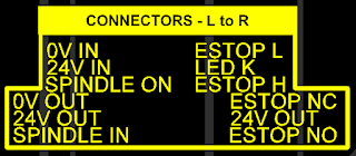 |
| Retrofit Rexon Controller Updated PCB Overlay |
Controller Option
To identify new features were added to the controller, one of the option resistors was populated on the controller PCB.
To identify new features were added to the controller, one of the option resistors was populated on the controller PCB.
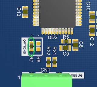 |
| Enabling Controller Option on PCB |
PSoC Code Changes
Additional changes were made in the code to read pulses measured by the spindle sensor counter and also to determine the configuration of the PCB version (function) resistors.
Option Resistors
Notes for the code option resistors was into the PSoC project.
The principal change to the PSoC was the addition of logic for counting pulses from the inductive sensor.
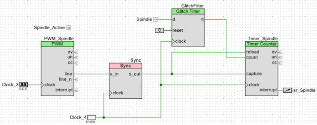 |
| PSoC Windowed Pulse Counter |
A timer solution was implemented fifty percent duty cycle with a period of 499 ms. During the On time the Timer_Spindle component accumulated counts from the Spindle input. At the end of the capture the isr_Spindle fires allowing the count value to be retrieved. For the remainder of the period no counting was performed. The Sync component was used to synchronise the slower PWM_Spindle clock with the Timer_Spindle clock.
Monitoring of the spindle active input and spindle speed was moved into a basic state machine, extract listed below.
Monitoring of the spindle active input and spindle speed was moved into a basic state machine, extract listed below.
/**
* @brief Basic State Machine for handling ESTOP and Spindle signals
*/

void State_Mach_Mon(void)
{
    switch (Spindle_Monitor_State)
    {
    case (state_m_idle):
        if (Status_ESTOP_Read() == 1u)
        {
            Spindle_Monitor_State = state_m_es_deact;
        }
    break;

   case (state_m_es_deact):
        Control_ESTOP_Write(0x1);
        if (Status_ESTOP_Read() == 0u)
        {
            Spindle_Monitor_State = state_m_reset;
        }

        if (Spindle_Active_Read() == true)
        {
            PWM_Spindle_Start();
            Timer_Spindle_Start();
            Spindle_Monitor_State = state_m_es_sp_act;
            Spindle_Started = true;
            Spindle_Timer = 100u;
        }
    break;

    case (state_m_es_sp_act):
        Spindle_Count_Update();
        if (Status_ESTOP_Read() == 0u)
        {
            Spindle_Monitor_State = state_m_es_reset;
        }

        if (Spindle_Active_Read() == false)
        {
            Spindle_Monitor_State = state_m_reset;
        }

        if ((Spindle_Counts == 0) && (Spindle_Timer == 0))
        {
           Spindle_Monitor_State = state_m_es_reset;
        }
    break;

    case (state_m_es_reset):
        PWM_Spindle_Stop();
        Timer_Spindle_Stop();
        Control_ESTOP_Write(0x0);
        Spindle_Started = false;
        if (Spindle_Active_Read() == false)
        {
            Spindle_Monitor_State = state_m_idle;
        }
    break;

    case (state_m_reset):
        Control_ESTOP_Write(0x0);
        PWM_Spindle_Stop();
        Timer_Spindle_Stop();
        Spindle_Monitor_State = state_m_idle;
    break;
    }
}
Additional changes were made in the code to read pulses measured by the spindle sensor counter and also to determine the configuration of the PCB version (function) resistors.
Option Resistors
Notes for the code option resistors was into the PSoC project.
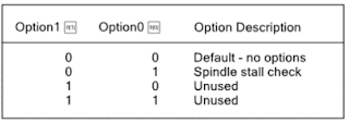 |
| PSoC Notes for Option Resistors |
In the PSoC code, the various resistor combinations were used to define the controller operation.
Sensor Counts
As the pulse counter configuration provided a 250 ms sampling window, the multiplier for the number of counts was set to 240.
The Report Data function was used to provide the spindle speed in RPM. Data was output on a UART as shown in the capture below from TeraTerm.
/**
* @brief Board Options
*/
void Board_Options(void)
{
    if ((Option0_Read() == false) && (Option1_Read() == false))
    {
        System_Flags.Option_None = true;
        UART_UartPutString("No option\r\n");
    }
    else if ((Option0_Read() == true) && (Option1_Read() == false))
    {
        System_Flags.Option_Spd_Mon = true;
        UART_UartPutString("Speed monitor option\r\n");
    }
    else if (((Option0_Read() == true) && (Option1_Read() == true)) || ((Option0_Read() == false) && (Option1_Read() == true)))
    {
        UART_UartPutString("Unknown option\r\n");
    }
}
Sensor Counts
As the pulse counter configuration provided a 250 ms sampling window, the multiplier for the number of counts was set to 240.
/**
* @brief Read Spindle Counts and Report
*/
void Spindle_Count_Update(void)
{
    if ((Spindle_Data_Ready == true) && (Spindle_Started == true))
    {
        Spindle_Counts = Spindle_Raw*240u;
        Spindle_Data_Ready = false;
        ReportData();
    }
    Flag_Timer = false;
}
The Report Data function was used to provide the spindle speed in RPM. Data was output on a UART as shown in the capture below from TeraTerm.
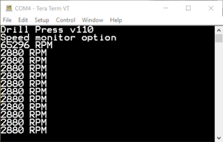 |
| Controller Spindle Speed Output in TeraTerm |
A timer, defined by variable Spindle_Timer, ensured that when the spindle was not spinning for one second, the drill press motor would be switched off using the contactor.
Final Thoughts
Final Thoughts
The controller in this blog could be adapted for other workshop machinery, which was not originally manufactured with a method to stop that machinery in a controlled manner. Features such as the spindle rotation monitoring could be removed or disabled and other features added to suit the machine setup.
Downloads |
| ESTOP v1.1 BOM XLS |
 |
| ESTOP v1.1 Schematics PDF |
 |
| ESTOP v1.1 PCB PDF |
 |
| ESTOP v1.1 Gerbers |
 |
| ESTOP v1.1 PSoC Doxygen |
 |
| ESTOP v1.1 PSoC 4.3 Project |
 |
| ESTOP Module PSoC Creator Top Design PDF |

