
As a follow-on from the original Beta Layout post, this information shows one method of connecting the Beta Layout reflow controller serial interface, to an Android compatible phone with some off the shelf hardware.
Reflow Controller
The Beta Layout Reflow Controller (V2) provides a connection to it's inner workings through a serial port (RS232), 9 pin D type connector. While moving a laptop to the reflow controller every time the controller requires and adjustment, there are devices such as the FTDI USB specific hardware to suit interfaces with Android phones.
USB Development Module
One of these devices, FT311, is a plug and play USB Host chip for Android devices. There is an associated development module, UMFT311EV, that provides a number of interfaces, one being RS232. The header pinouts on the module suits off the shelf adaptor boards and some shields.
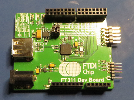 |
| FTDI FT311 Dev Module |
The FTDI board is TTL so an RS232 shield such as the model from DFRobot can be used to make the required conversion.
 |
| DFRobot RS232 Shield |
While the 5V and 0V power header is pin compatible between the boards, the communications header with TX, RX, CTS and RTS requires a few jumpers.
From Section 4.1.2 of the UMFT311EV datasheet the hardware connections are identified.
 |
| UART Hardware Pinouts |
Since the hardware handshaking is not used these two pins 5 and 6, can be joined together for now.
 |
| DF Robot J1 Pinouts |
The corresponding Tx and Rx connections as shown on the DF Robot shield schematic, follow the Arduino shield mapping and are available on pins 1 and 2.
To make the modifications, pins 1 and 2 on the Robot shield are snipped off or pulled to the side as not to mate with the FT311 development module.
 |
| DF Robot Jumper Connections |
Using wire links or a pin header inserted into J1 on the Robot shield, pin 1 RXD is linked to pin 4 or RXD for the USB. Then pin 2 TXD is linked to pin 3 or TXD for the USB. Lastly pins 5 and 6, CTS and RTS are linked.
The FT311 module and Robot shield can be fitted together.
RS232 Cable
Since both the communications devices sport a 9 pin female D connector a null modem cable is required between them.
Hardware Assembly
The other two pieces of hardware required are a power supply or plug pack to suit the development module and the USB charging cable used with the Android phone.
 |
| Assembled FT311 and RS232 Shield Hardware |
Android Terminal Program
To communicate with the Development board FTDI provide AOA HyperTerm, which is a basic terminal interface for the Android. Available on the Google Play Store and passes the Android MyPermissions and 360 Security checks.
With the HyperTerm application installed and the hardware setup powered then phone can be connected to the charging cable. In doing so the HyperTerm application is automatically launched.
 |
| AOA HyperTerm Application from FDTI |
 |
| AOA HyperTerm Communications Settings |
After selecting Configure commands can be exchanged with the reflow controller.
 |
| AOA HyperTerm Communications Settings Confirmation |
Starting with sending help and a CR the list of available commands is returned.
 |
| Beta Layout commands on AOA HyperTerm |
In the screenshot above the help screen and status data is displayed in the HyperTerm window. The status information is configured for bursts at five second intervals which is used to track the starting and operational temperatures.
The final setup of the hardware as used on the bench is shown below. For similar and compatible Android USB hosts, shields or development kits the same process should be possible!
 |
| Beta Layout, USB Dev Kit, RS232 Shield with Android and AOA HyperTerm |