Tuesday 22 May 2018

Delta (AFB1212SHE) Fan Testing

Summary
This blog covers some basic measurements of the Delta (AFB1212SHE) DC brushless fan with a possible use of the fan for computer cooling.


Delta AF1212SHE DC Brushless Fan
Hardware Setup
To perform measurements of the current drawn by the fan across and a range of input voltages, the displayed values on from a Rigol DP832 power supply were utilised. For the tacho measurements a Cypress CY8CKIT-049 development board was employed to convert the tacho output from the Delta fan into a corresponding RPM value.


CY8CKIT-049 - Courtesy Cypress Semiconductor


For the PSoC input a pullup resistor (4k7) was connected between the 5V DC supply and the input pin.


PSoC - Delta AFB1212SHE Test Bed
PSoC Tacho Measurement
The tacho measurement solution utilised a one second sampling window to count the number of pulses. While the measurement solution does have some level of jitter, this was unimportant as the measurement was for indicative purposes.


PSoC Tacho Measurement

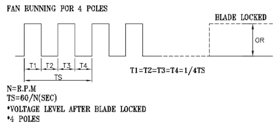
The website documentation for the Delta brushless fan, AFB1212SHE-F00 shows that the fan has 4 poles and two pulses are seen for each complete rotation of the fan. The image below is taken from the fan datasheet.


Delta AFB1212SHE Tacho Output

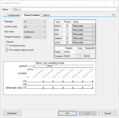
The Cypress Timer_3 component performs all the counting and is configured to count on rising edges. A copy of the project is available at the end of the blog for anyone wanting to review and improve the design.


PSoC tacho Timer Component Configuration

Measurement results of the fan speed were made available on the Kitprog serial connection. 

Measurement Results

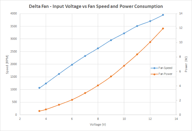
While varying the input voltage across the operating range listed on the Delta website, the fan speed was calculated and output to a serial monitor. The DC power consumption was calculated and plotted against the fan speed. 

Shown in the graph below is the almost linear relationship between input voltage and fan speed.


Delta AFB1212SHE Input Voltage vs Fan Speed and Power Consumption

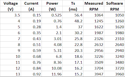
The data listed below represents the points in the graph above. There is also one addition to the table which is Measured RPM. This value was derived using the period of the Tacho waveform to verify the error in the PSoC software measurement.


Measurements with Delta AFB1212SHE

Tuesday 1 May 2018

PSoC 5 Bootloader USB vs UART I2C Speeds

Summary
This purpose of this blog was to test the download speeds of a PSoC 5 development kit using the KitProg I2C, UART and compare the results against the on-board USB to PSoC interface. 

Test Hardware
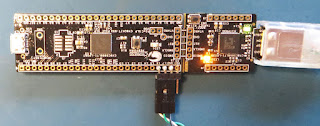
A Cypress PSoC development kit CY8CKIT-059 was used with a PSoC Creator project that was configured to test the KitProg SCB I2C and UART components, then secondly a SCB UART connected to an external adaptor and lastly USB interfaced directly to the PSoC 5 with the relevant USB component.


CY8CKIT-059 with External UART Header
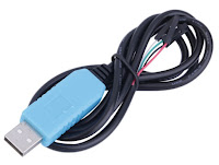
For UART testing which did not use the Kitprog interface a separate USB to Serial converter from Prolific was utilised. The adaptor was the same type, USB to TTL Serial Cable - Debug / Console Cable for Raspberry Pi from Adafruit as used in a previous blog for similar PSoC 4 tests. The TTL connections to the Prolific adaptor, Black wire was connected to 0V, White to pin P1.6 and Green to pin P1.7 of the Cypress Kit.


Prolific USB to TLL Converter
For the Kitprog UART connections in PSoC Creator, P12.7 was used for Tx and P12.6 for Rx. Kitprog I2C connections in Creator used P12.1 for SDA and P12.0 for SCL. 

Test Software
As used in a previous blog, a Creator project related to the DS18B20 was used as the bootloadable component for testing. There were some changes moving between the original PSoC 4 based project to the PSoC 5. These changes resulted in a file size change from 20kb to 28kb.

Where possible, the PSoC Creator PSoC 5 example USBFS project had only minimal changes applied. The PLL Clock was adjusted to achieve the best results for the UART clock when PSoC Creator displayed tolerance warnings. 

Reference Download USB
There were no misgivings that a direct USB interface into the PSoC 5 would result in a fast bootloader time - in fact, the result was almost immediate - for such a small bootloadable file!

UART Download
There is a technical document from Cypress regarding the Kitprog hardware bridge communications speeds for the PSoC5 Development Kit. On page 6 of the Kitprog document is a table showing the programming speed limits for the various interfaces, as shown below.


Kitprog User Guide Table 2-3
Of interest are the maximum speeds for the I2C and UART facilitated by the USB bridge. In the Cypress community forum there is a thread stating that faster communications speeds are possible, however this is not covered by this blog.

It should be noted that the external Prolfic USB to TTL adaptor hardware is capable of data rates far in excess of the 921600 maximum listed in the Cypress Bootloader Host.

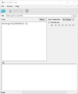
Cypress Windows Bootloader Host
For all the download test performed, the Cypress Bootloader Host was used from within PSoC Creator. The other standalone Windows application known as Cypress UART Bootloader application supports baud rates to 115200 only.


Cypress Bootloader Host
Baud Rate Clocks (SCB)
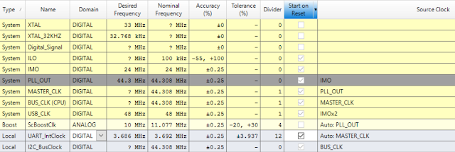
The change to the PLL clock in the Creator project, as shown below, was required for baud rates above 230400 baud. This clock change was implemented due to the warning raised by PSoC Creator relating to clock accuracy.


PSoC Creator Clock Tolerance Warning

An change to the clock was instigated under the Clock tab in Creator's Design Wide Resources. The PLL Out Clock was reduced from 48Mhz to 44.3MHz when using the UART with the external Prolific adaptor.


PSoC Creator Change to PLL Out Clock

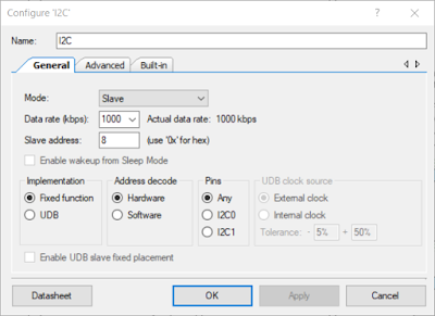
I2C Configuration
For the Slave I2C, the data rates were changed from 50 to 1000kbps in the PSoC Creator component.


PSoC Creator I2C Component Configuration

A corresponding change was made to the Bootloader Host application to match the data rate.


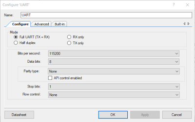
UART Configuration

The UART was configured in the same manner for tests using Kitprog and the Prolific adaptor.


UART SCB Component Configuration
For the Bootloader component the Tx and Rx buffer were configured for 64 bytes as required.

Test Results
Listed below are the test results for the USB, UART and I2C communications.
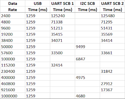

Cypress Bootloader Download Times for PSoC5
A few items should be noted in the above table. Firstly the USB speed is 'constant'. Appropriately the Cypress Bootloader Host application does not display a baud rate option when the PSoC5 USB port is selected. Secondly the Kitprog UART and I2C interfaces operate to 115200 baud and 100,000 khz as detailed by Cypress.

Graphing the results provides a pertinent visual of how much faster the USB interface, shown in blue, is over Kitprog or a standard UART interfaces. The Kitprog I2C interface does deserves an honourable mention as it closer in download times to the USB compared to UART.
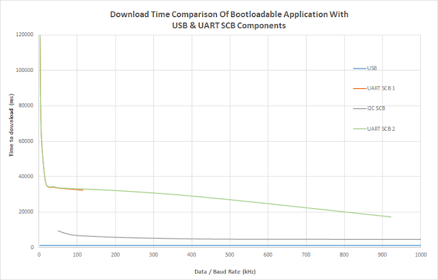

Graphed Cypress Bootloader Download Times for USB, I2C and UART


Code and Project
The code snippet for the Bootloader application as taken from the Cypress USB PSoC 5 example is listed below.

/*******************************************************************************
* File Name: main.c
*
* Version: 3.0
*
* Description:
*  This example project demonstrates the basic operation of the Bootloader and 
*  Bootloadable components when the communication interface is a USB.
*
********************************************************************************
* Copyright 2015, Cypress Semiconductor Corporation. All rights reserved.
* This software is owned by Cypress Semiconductor Corporation and is protected
* by and subject to worldwide patent and copyright laws and treaties.
* Therefore, you may use this software only as provided in the license agreement
* accompanying the software package from which you obtained this software.
* CYPRESS AND ITS SUPPLIERS MAKE NO WARRANTY OF ANY KIND, EXPRESS OR IMPLIED,
* WITH REGARD TO THIS SOFTWARE, INCLUDING, BUT NOT LIMITED TO, NONINFRINGEMENT,
* IMPLIED WARRANTIES OF MERCHANTABILITY AND FITNESS FOR A PARTICULAR PURPOSE.
*******************************************************************************/

#include <main.h>


/*******************************************************************************
* Function Name: main
********************************************************************************
*
* Summary:
*  The main function performs the following actions:
*   1. Indicates that the bootloader project is running by turning on the LED.
*   2. Starts the bootloader component and it waits for the application update. 
*      After 10 seconds, the code jumps to the application if it is available. 
*      Otherwise waits forever for application upload.
*
* Parameters:
*  None.
*
* Return:
*  None.
*
*******************************************************************************/
int main()
{
    /* Indicates that the bootloader is running. */
#if (CY_PSOC4)
    RGB_LED_ON_RED;
#else
    TURN_ON_LED4;
#endif /* (CY_PSOC4) */

    /* Enters the bootloader to wait for the application update. */
    Bootloader_Start();

    /* Bootloader_Start() never returns. */
    for (;;)
    {
    }
}


/* [] END OF FILE */
 

Lastly the PSoC 5 project which contains the Bootloader and Bootloadable applications.


Bootloader - Bootloadable Test Application