Summary
This post illustrates the benefits of using timing diagram software for debugging and project documentation. Examples of timing software packages used for various purposes include Timing Editor, WaveDrom, Timing Analyser and Waveme. The implementation in this blog is presented using the JavaScript tool, WaveDrom integrated with Blogger. All credit to the original developer!
Note than the inline Javascript (Wavedrom images) may not execute or display on mobile browsers.
WaveDrom Timing Example
To illustrate a known issue with timing, the input and output states of a controller in a previous blog were used. The timing diagram below captures the power up state, states when a button was pressed then released and lastly the effect of a firmware controlled signal for disabling a hardware output.
The unhandled state was only located after testing however drafting the diagram shows an unhandled state when the firmware controlled signal changes to false. This issue is identified on the timing diagram with the markers a-b and comment 'state'.
For the WaveDrom generated timing diagram shown above, the editor implementation is detailed below.
{signal:
 [
   {name: 'PSoC Firmware' , wave: '07|.................', node: '....................' },
   {name: 'Control ESTOP' , wave: '05|.............0...', node: '....................' },
   {name: 'ESTOP IN1' , wave: '0.|.5....0....5.....', node: '....................' },
   {name: 'ESTOP IN2' , wave: '0.|.5....0....5.....', node: '....................' },
   {name: 'Contactor'   , wave: '0.|..5....0....5..0.', node: '....................' },
   {name: 'ESTOP LED'   , wave: '0p|...5....n..05....', node: '..................a.b' },
],
  edge: ['a->b STATE'],
  config:{skin:'default'},
  head: {text: 'ESTOP Controller'}
}WaveDrom for Documentation
WaveDrom has an additional feature referred to as Reg which refers to register. This feature can be used for documenting the function of bits in registers.
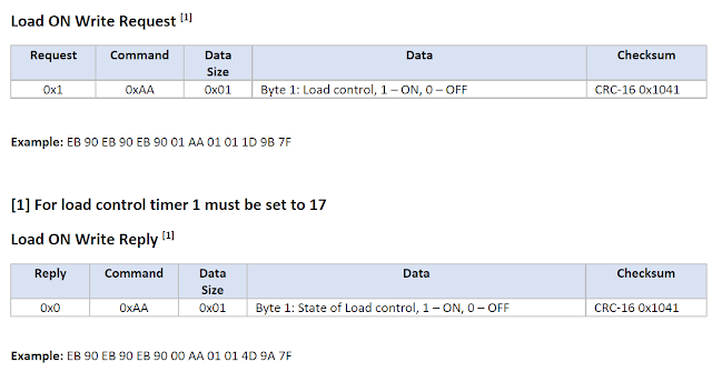
As an example of the register feature, the communications packet for a Tracer RN series MPPT was extracted from an older blog. Originally the Tracer protocol document was created (updated) in MS Word then published as a PDF for distribution on the web.
Below is an example Tracer RN command packet taken from the protocol document.
 |
| Tracer Documentation in MS Word |
For the register that is displayed above, the WaveDrom editor implementation is shown below.
{reg:
[
  {bits: 2,  name: 'End', attr: ['0x7F'], type: 5},
  {bits: 4,  name: 'CRC', attr: ['CRC16', 'x1041','Bits 13:6'], type: 2},
  {bits: 2,  name: 'Ctrl', attr: ['ON = x01', 'OFF = x00'], type: 4},
  {bits: 2,  name: 'Size', attr: 'x01', type: 4},
  {bits: 2,  name: 'Cmd', attr: 'xAA', type: 4},
  {bits: 2,  name: 'Req/Reply', attr: ['Req x01', 'Rep x00'], type: 4},
  {bits: 12,  name: 'Head', attr: ['xEB x90 xEB x90 xEB x90'], type: 5},
],
  config:{bits: 26}
}
WaveDrom with Doxygen
WaveDrom diagrams and registers can be displayed in the Doxygen generated output using the Doxygen htmlonly special command. This special command can be used in usual source, header and markdown (.md) files.
Generating the main page output shown above was achieved using the contents of the markdown file detailed below. Doxygen was tweaked to display a navigation tree.
/** @mainpage Register Example
@htmlonly
<script src="https://wavedrom.com/skins/default.js" type="text/javascript"></script>
<script src="https://wavedrom.com/WaveDrom.js" type="text/javascript"></script>
 <script type="WaveDrom">
 {reg:
[
  {bits: 2,  name: 'End', attr: ['0x7F'], type: 5},
  {bits: 4,  name: 'CRC', attr: ['CRC16', 'x1041','Bits 13:6'], type: 2},
  {bits: 2,  name: 'Ctrl', attr: ['ON = x01', 'OFF = x00'], type: 4},
  {bits: 2,  name: 'Size', attr: 'x01', type: 4},
  {bits: 2,  name: 'Cmd', attr: 'xAA', type: 4},
  {bits: 2,  name: 'Req/Reply', attr: ['Req x01', 'Rep x00'], type: 4},
  {bits: 12,  name: 'Head', attr: ['xEB x90 xEB x90 xEB x90'], type: 5},
],
  config:{bits: 26}
}
 </script>

<script type="text/javascript">
(function() {
    try {
        WaveDrom.ProcessAll();
    } catch(e) {}
})();
</script>
@endhtmlonly

The structure of the communications register is as detailed above...
