Summary
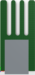
This blog presents a design concept for a jig which would suit the manufacture of a small cable harness. The jig consists of the usual bottom board (base) and separate boards (inserts) which screw into the base. As with existing cable harness solutions, the purpose of the inserts is to assist during the production of the cable harness.
Existing Solutions
For the production of a cable harness, a jig or layout board is commonly used. Companies such as Panduit provide scalable solutions, such as the Quick Built kit.
 |
| Quick Build Kit - Courtesy Panduit |
Solutions such as the Panduit layout boards are supplied with a multitude of clips, holders and ties for looming the cable harness.
Small Layout Board
Consider a prototyping or pre-production run of a cable harness. The harness may not be complex or necessarily time-consuming to manufacture however, the ability to reliably reproduce the loom may be an important consideration.
The jig base depicted in the image below is a 300 mm square sheet of fibreglass (PCB) with PCB mount posts (PEM). Any sturdy material could be used as the base with many layout boards produced from wood (MDF, plywood) or plastic.
 |
| Example Base Board (FR4) |
The design uses PEM’s with a 10 mm spacing between all PEM's. A custom spacing or arrangement for the PEM's could be used with the design.
 |
| Example Base Board PEM 3D |
Wiring Adaptors
Connecting to the PEM’s are the adaptor boards. These adaptors are fitted to PEM's in the base using M3 male to male hex spacers. All the machined metal is a significant expense. A more cost-effective solution than the hex spacer may be a half threaded bolt or eye bolt. These bolts could be soldered directly to the adaptor PCB.
 |
| Example Eye Bolt |
The following section details five example adaptors for various cable harness tasks. Each PCB is 8 mm wide and 16 mm tall.
Adaptor 1
Stranded cable adaptor.
 |
| Adaptor 1 |
Adaptor 2
Trunk or sheathed loom adaptor.
 |
| Adaptor 2 |
Adaptor 3
Holder for cables end terminated with connectors such as SMA style.
 |
| Adaptor 3 |
Adaptor 4
Corner for stranded, trunk or sheathed loom.
 |
| Adaptor 4 |
Adaptor 5
Holder for cables whtch are end terminated with crimp style connectors.
 |
| Adaptor 5 |
Pricing
From a PCB manufacturer such as JLCPCB, the two-sided base board was approximately USD 7 at the time of publishing. Each adaptor board was a fixed size of 16 x 8 mm. These boards were less than USD 2 each from the same supplier.
Certainly, the bulk of the hardware cost resides in the mounting hardware; PEM's, standoffs and PCB mount blocks. Simplifying the mounting scheme between the base board and the adaptors or manufacturing a custom mounting would provide an optimum solution.
 |
| Example of Base Board Loaded with Adaptors |
Final Thoughts
As mentioned, the jig detailed in this blog was a design concept only. The design was not manufactured or tested because the requirement for this design was no longer applicable. A variant of this design may be realised or improved for open source applications.
Downloads


