Summary
This blog describes how salvaged electronic hardware, such as circuit boards, can be repurposed for alternative tasks.
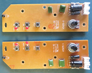 |
Salvaged Circuit Boards from Kitchen Appliance
|
Overview
The board (PCB) described in the blog was removed from a kitchen appliance (toaster) when repairing the appliance was not possible. When a requirement came for a basic timer, rather than scrounging for a 555 timer to place on Veroboard or trawling the web to purchase a microcontroller to use as a timer, the toaster PCB was recalled. Time to play!
PCB Description
Used on the PCB was an integrated circuit (IC) from CMSemicon (China), part CMS12530. The CMS device represents the brain of the operation, performing timing and output control. The additional pushbuttons define the operations and the potentiometer to vary the timers operating time.
 |
Salvaged PCB Solder Side
|
Since the PCB was a simple design, it was decided to transpose the circuit into Altium Designer, as pictured below.
 |
| CMS12530 Circuit from Salvaged Appliance |
The operating voltage of the PCB hardware was not determined during the salvage operation, so a low input voltage was selected for testing.
PCB Testing
A bench power supply providing DC 12 V was connected to the connector IN. After powering the PCB, pressing the Defrost or Reheat buttons resulted in the corresponding LED switching ON however the LED did not switch OFF.
No wiring had been made to the PCB OUT connector. It was determined that the output transistor Q1 was normally ON after power-up, then switched OFF after the timer had expired.
The push to activate function of the toaster needed to be simulated. To achieve this function, a latching relay utilising a single contact was added to the circuit.
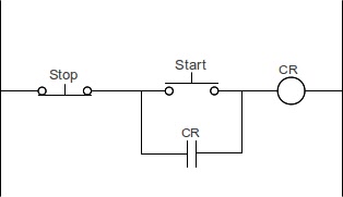 |
Start-Stop Control Courtesy Accautomation
|
With the addition of a push-button (Start), the relay could be latched. The stop operation was resolved using the output transistor.
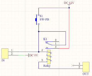 |
Circuit to Power Salvaged Appliance PCB
|
When the start button S1 was pressed the relay latched and the CMS controller began timing. If no buttons on the PCB were pressed, the timing operation was normal. Otherwise, the Defrost, Reheat or Stop button operation took precedence.
 |
Connections to Salvaged Appliance PCB
|
After the timing cycle was completed by the controller, the transistor Q1 unlatched the relay thereby disengaging power to the PCB. Reactivation of the timer required the Start button to be pressed again.
Summary
The reverse engineering and initial testing in this blog were sufficient to verify that the salvaged PCB could be repurposed as a basic timer. The PCB in this blog would not be recommended for commercial or industrial purposes, however until the supply of global electronics return to a stable level, the use of salvaged electronic hardware may provide value for specific solutions.
