Introduction
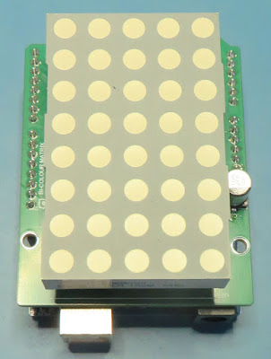
This blog shows the hardware used for an Arduino-compatible shield
featuring a dual-colour matrix LED.
 |
| LED Matrix Shield Mounted on Arduino Uno |
Purpose of the LED Matrix
The design was created for educational purposes and to train
school-aged programmers. For hobbyists looking for an off-the-shelf solution
using LEDs, some related products featuring RGB LEDs are the
NeoPixel
or for an LED matrix, the D1 Mini from
Wemos.
Technology Used
Three shift registers,
part 74HC595, were used to drive the 8 rows and 10 columns (matrix 5 red and 5 green
LEDs) of the LED matrix from the Arduino Uno. To maintain the design simplicity, no LED
buffers were included which would increase the drive current. The 74HC595
from Nexperia fitted to the prototype could provide 25 mA per pin although
the maximum current of the shift register is limited to approximately 70 mA.
A buck converter, TI part LMR51606YDBVR was chosen to provide 5V power to the shift register and LED matrix. A higher current DC-DC converter and LED drivers could be utilised for a brighter LED matrix.
 |
| Kingbright Dual Colour LED Matrix |
For the
LED matrix, Kingbright part TBC24-11EGWA was used. At the time of writing
the LED Matrix from Kingbright part had become End of Life.
Connections to Arduino
Details are provided on the Arduino website for connecting shift
registers such as the 74HC595 to the Uno board. One such example with connections and
code is shown in the
tutorials.
The shift register connections to the Arduino are the same as the tutorial with the addition of the output enable signal.
To adjust the LED matrix intensity and depending on the characteristics of LEDs, the value of the resistor packs could be changed. During testing the values 68 R and 56 R for red and green LEDs respectively achieved a good balance between current consumption and light output.

|
|
LED Matrix Shift Register Connections |
Shown in the image below are the pins used on the Arduino Uno for the shift registers and power.

|
|
| LED Matrix Shift Register to Arduino Connections |
Lastly, a DC-DC converter was used instead of the linear regulator on the Arduino Uno. This meant less heat dissipation on the Uno board.
 |
| LED Matrix Power Supply |
Printed Circuit Board (PCB)
The PCB for the LED matrix shield was designed with four layers however the board layer count could be reduced. Shown below are the external power and internal signal layers. The top layer was a solid copper pour for the 0 V layer and therefore not shown.
 |
| LED Matrix Bottom Layer PCB |
 |
| LED Matrix Mid Layer PCB |
 |
| LED Matrix Mid Layer PCB |
Populated LED Matrix
The completed prototype board used pin headers for the LED matrix although the PCB was designed to allow flush mounting of the LED matrix.
 |
| Populated LED Matrix Shift Register Side |
 |
| Populated LED Matrix (Display) Side |
When connecting the LED matrix shield to an Uno or similar board, a space between the two boards of at least 13 mm was required. This spacing ensured the LED matrix pins did not cause a short against the USB B connector housing.
 |
| Arduino Uno and LED Matrix Fitted Together |
LED Matrix Operation & Code
For the example below the Arduino pin mapping shown below was used.
void setup()
{
  pinMode(latchPin, OUTPUT);
  pinMode(clockPin, OUTPUT);
  pinMode(dataPin, OUTPUT);
  pinMode(oePin, OUTPUT);
  digitalWrite(oePin, LOW);
}
Counting with Rows
  for (int numberToRows = 0; numberToRows < 255; numberToRows++)
  {
    digitalWrite(latchPin, LOW);
    shiftOut(dataPin, clockPin, MSBFIRST, 0);           // red = 0, all off 31 show green
    shiftOut(dataPin, clockPin, MSBFIRST, 0);           // green = 0, all off 31 show red
    shiftOut(dataPin, clockPin, MSBFIRST, numberToRows);   // turn on all columns
    digitalWrite(latchPin, HIGH);
    delay(100);
  }
for (int numberToColumns = 0; numberToColumns < 32; numberToColumns++)
{
digitalWrite(latchPin, LOW);
shiftOut(dataPin, clockPin, MSBFIRST, numberToColumns); // red = 0, all off 31 show green
shiftOut(dataPin, clockPin, MSBFIRST, numberToColumns); // green = 0, all off 31 show red
shiftOut(dataPin, clockPin, MSBFIRST, 255);// turn on all rows
digitalWrite(latchPin, HIGH);
delay(100);
}
Dual Colour Change
  digitalWrite(latchPin, LOW);
  shiftOut(dataPin, clockPin, MSBFIRST, 0);   // red = 0, all off 31 show green
  shiftOut(dataPin, clockPin, MSBFIRST, 31); // green = 0, all off 31 show red
  shiftOut(dataPin, clockPin, MSBFIRST, 255); // turn on all rows
  digitalWrite(latchPin, HIGH);
  delay(200);
  digitalWrite(latchPin, LOW);
  shiftOut(dataPin, clockPin, MSBFIRST, 31);    // red = 0, all off 31 show green
  shiftOut(dataPin, clockPin, MSBFIRST, 0);     // green = 0, all off 31 show red
  shiftOut(dataPin, clockPin, MSBFIRST, 255); // turn on all rows
  digitalWrite(latchPin, HIGH);
  delay(200);
Downloads
 | |
| LED Matrix Gerber | |
 |
| LED Matrix Schematic |
 |
| LED Matrix Top Overlay |
 |
| LED Matrix Bottom Overlay |
