Summary
This blog continues from part 2 of the supply voltage interruption tester (unit) post.
Covered in this blog is an overview of the unit assembly and code functionality.
Unit Assembly
The display printed circuit board (PCB) contains a display (LCD) that requires mounting. The associated LCD hardware consists of M2.5 bolts, washers and spacers.
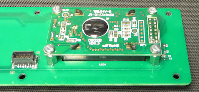 |
| Interruption Tester Mounted LCD |
For the connection between the display and power PCBs, surface mount connectors were used. Due to global supply constraints, this connector pair will be changed on a future PCB revision.
For the complete unit assembly, an anodised metal enclosure (Multicomp Pro MC002177) was utilised. The front and power PCB are fitted via the surface mount connectors and then slid into the enclosure. PCB slots are provided at various heights on the inside walls of the enclosure. To mount the front panel PCB, six bolts are required.
 |
| Interruption Tester Front Panel |
The rear panel is placed over the banana connectors and held in place with a further six bolts.
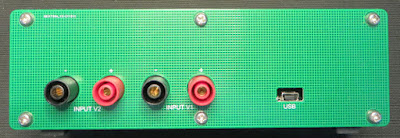 |
| Interruption Tester Rear Panel |
Rubber feet were fitted to complete the assembly.
Code Summary
The Infineon (Cypress) PSoC project is a standalone application targeted at the device CY8C4245AXI-483. The roadmap for the Interruption Tester project contains a firmware change to use the PSoC bootloader to suit field upgrades.
The project code is broken into three sections which relate to the user interface buttons, LCD and output drivers. These handlers interface with PSoC digital blocks by way of a system timer, Capsense, LCD, PWM and other interfaces.
 |
| PSoC Capsense Component |
For the Capsense button handler, the 5-element radial Capsense (slider) value is processed which allows the selection of the LCD menu item.
The On/Off (Output) button is processed through a state machine that performs a latching/unlatching action on the button press.
 |
| Capsense Scan Configuration |
When the output is Off, the LCD presents a test number, that relates to the pre-programmed tests detailed in the following section.
While the output is activated (On), the selection of other tests is not possible. The PWM blocks are programmed for continuous operations.
The display handler uses details from the button handler for the management of display strings.
 |
| PSoC LCD Component |
The LCD has other tasks such as throwing up the boot screen or error states when applicable.
The output handler uses details from the button handler to configure PWM, configure the multiplexers and activate the high-side drivers. The two high-side drivers individually switch two input voltages, Voltage 1 (V1) and Voltage 2 (V2).
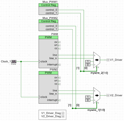 |
| PSoC PWM and Multiplexer Components for Output Stage |
Summary of Programmed Tests
Five tests are programmed with each test summarised below.
The term dipping, as described in the IEC standard, refers to the power supply changing voltage compared to interrupting which refers to the power supply switching OFF.
Test 1 - 10 ms pulse width interrupting Voltage 1 (V1) at a frequency of 10 Hz. Voltage 1 is switched OFF.
 |
| Interruption Tester - Test 1 Output No Load |
Test 2 - 20 ms pulse width dipping Voltage 1 (V1) at a frequency of 5Hz. Voltage 1 is switched OFF and Voltage 2 will be supplied during V1 off time.
 |
| Interruption Tester - Test 2 Output No Load |
Test 3 - 500 ms pulse width dipping in Voltage 1 (V1) at a frequency of 0.2 Hz. Voltage 1 is switched OFF and Voltage 2 will be supplied during V1 off time.
 |
| Interruption Tester - Test 3 Output No Load |
Test 4 – 1.8 ms pulse width dips in Voltage 1 (V1) at a frequency of 50 Hz. Voltage 1 is switched OFF.
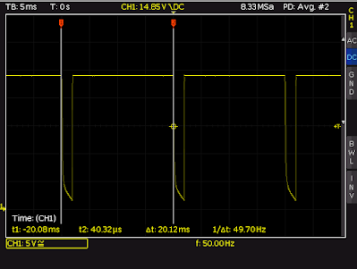 |
| Interruption Tester - Test 4 Output No Load |
Test 5 – Approximately 280 us pulse width (spikes) at a frequency of 100 Hz. Voltage 1 remains ON and Voltage 2 will be switched ON to generate the spike.
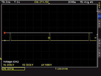 |
| Interruption Tester - Test 5 Output No Load |
The IEC standard states that the equipment under test (EUT) should be subject to ten dips. Updates to the code could allow for the dips to be limited to ten. The tests currently continue to run.
Tests 1 through 3 allow for basic testing to the IEC standard.
Test 4 was created for verifying filters targeting 50 Hz.
Test 5 can be used with an oscilloscope to check the performance of devices and designs using protection diodes. These diodes may include steering or Transient (Tranzorbs) diodes. A narrow pulse (spike) is applied for a short time at a frequency of 100 Hz. The frequency may need to be adjusted for applications where the protection diodes are low power.
Tests 1 and 2 are classified as B tests meaning that the operation of the EUT should not be changed as a result of the test. Test 3 is classified as a C-test which means that the EUT can fail in a known condition.
More in post four
