Introduction
This blog shows testing of circuit board mouse bites that have copper traces passing through them. The breaking strength of the mouse bite was also measured during testing.
 |
| Mouse Bite Test Boards |
Mouse Bites
The use of mouse bites with circuit boards can be as varied as the application however, some common examples of applications include board panelisation, tooling strips, test coupons, in-circuit testing or breakaway boards. This blog’s focus is on small breakaway boards commonly used in embedded programming or development boards where traces are routed through the mouse bites.
SparkFun published a white paper in 2022 (Author, Nick Poole) that illustrated testing of various mouse bite combinations. The paper from SparkFun serves as a good reference for designer as it details the combinations and the force required to break the board under test (mouse bite).
This blog performs similar tests to those conducted by SparkFun however, the intent was also to see the effect of circuit board traces after breaking the mouse bites.
Test Board
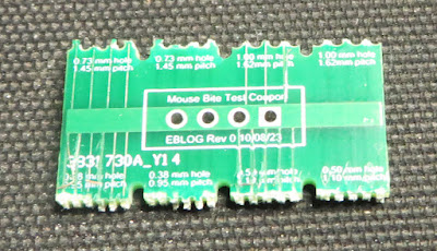
A circuit board was created with four mouse bite configurations. The drill hole sizes varied between 0.38 mm to 1.00 mm. The pitch between holes was adjusted to suit the drill size and test boards.
 |
| Test Board for Mouse Bites |
Between the holes of the mouse bites, traces were routed either externally (top and bottom) or internally traces (two mid-layers). This created eight combinations of trace and mouse bites for testing.
 |
| 3D View of Test Board for Mouse Bites |
Measurements
For each mouse bite break measurement, a simple setup containing an attachment to the test board and connecting wire to a digital scale was used.
 |
| Mounted Test Board |
 |
| Measurement Tool |
Results
The table below lists the test number against the mouse bite drill size and pitch combination.
 |
| Mouse Bite Configurations |
As seen in the chart below, there was little difference in test results between the various mouse bite configurations and lifted board traces. External board traces on average lifted on the opposite side of the circuit board. Any lifted traces were considered damaged. No internal traces were seen to be damaged.
 |
| Type vs Listed Traces After Testing |
The chart beneath shows the average measurement (kg) required to break the mouse bite boards. A notable difference in the last two tests was expected because of the larger mouse bite holes meaning less circuit board material.
 |
| Type vs Measurements for Breaking Mouse Bites |
The edge view of the main board in the image below shows the different breakage patterns.
 |
| Circuit Board Edge with Mouse Bites Removed |
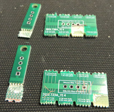
During two measurements, the test board broke cleanly except for one layer that lifted and tore away from the main board; as shown in the picture below.
 |
| Damaged Test Boards |
Summary
The results in this blog with the specific test board indicate that internal traces experienced fewer issues with lifted traces. Other combinations of routing such as using a single side for external traces will likely be effective.
 |
| Mouse Bite Test Piece |
For designs only requiring mouse bites in a circuit board design, most hole-pitch configurations are useable although the overall design should be reviewed as part of Engineering practices.
