Introduction
In this blog, a modification was made to the generic 9.8” pottery wheel supplied by Amazon. A connector was fitted to allow the foot pedal to be removed.
 |
| Amazon Pottery Wheel (Courtesy Amazon) |
Pottery Wheel Foot Switch Cable Location
Protruding from the underside of the pottery wheel is a white cable that connects the foot pedal to the pottery wheel’s electronic controls. The connection of the white cable was altered to fit a connector allowing disconnection for movement or storage of the pottery wheel.
 |
| Underside View of 9.8" Pottery Wheel |
The white cable passes through a hole in the pottery wheel's metal chassis. The hole's internal diameter is approximately 14.8 mm. Depending on the type of chassis mount connector selected, the hole may already be suitable for that connector. Alternatively, an inline pluggable connector could be fitted instead of the chassis mount connector.
An M12 chassis mount and an inline connector set from TE Connectivity was chosen for this project.
Pluggable Connectors
Fitting the M12 chassis mount socket connector started with cutting the white cable. Sufficient cable length was left protruding through the hole to allow for connecting to the chassis mount connector. The cable was moved to the side temporarily while the hole was made larger with a stepped drill bit.
The three wires in the foot pedal cable, red, yellow and green were stripped and tinned. A small length of heatshrink was fitted on each wire. The cable was passed through the retaining nut and then the hole in the chassis. The wires protruding through the hole were soldered to the M12 socket.
 |
| Pottery Wheel Side - M12 Chassis Mount Socket |
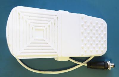
For the mating side of the connector, an M12 plug was fitted to the cable attached to the foot pedal.
 |
| Foot Switch Side - M12 Inline Plug |
The M12 TE Plug used screw terminals instead of solderable pins. The stripped wires were connected in the same order as the socket.
An operational test was performed before finalising the heatshrink and tightening the M12 nut.
 |
| Pottery Wheel M12 Connector Test Fit |
The assembled foot switch is pictured below.
 |
| Updated Foot Switch Assembly |
The connected assembly of M12 connectors is shown below.
 |
| Completed M12 Connector Assembly |
