Introduction
The Printed Circuit Board (PCB) design in this post was inspired by the well-known signal integrity educator, and professor, Eric Bogatin. The board design was based on content shown in a YouTube video created to demonstrate crosstalk.
 |
| Crosstalk PCB 3D |
Why This Design?
Following on from the PCB trace-to-trace crosstalk content created by YouTuber Robert Feranec with guest Eric Bogatin, I wanted to design a simple educational board that would allow crosstalk measurements to be made on a PCB and tested when passive elements were introduced into PCB traces. Crosstalk measurements with series and parallel resistor signal path terminations are common in many PCB designs and this PCB design was designed specifically for series terminations.
Circuit Board Design
A regular 1.6 mm board (FR4) double-sided PCB was chosen for the design. For the copper layers, a reference plane was placed on one side of the PCB and impedance-controlled traces were placed on the opposite side. Using PCB design software tools, the configuration of the trace impedance (width) was tuned for around 50 R impedance giving a 2.8 mm trace width. The 50 R impedance is given a tolerance of + 10 % as this is the standard tolerance for PCB fabrication houses in the local region.
 | |
| Altium Impedance Profile 50 R for Crosstalk PCB | |
As a crosstalk PCB design features two signal traces, the spacing between the traces was set at less than a track width to ensure ample signal coupling between traces.
 |
| Crosstalk PCB 2D |
As the series element, a resistor footprint was included in one of the PCB test traces.
 |
| Crosstalk PCB Resistor Linked |
This footprint on the PCB provided an option to test with different resistor values and then measure the effects with suitable test equipment. A pulse generator with a fast edge and an oscilloscope are required.
The first setup on the test PCB has the series resistor on the same layer as the signal trace and the second test setup has the resistor on the opposite side to the trace, connected through vias.
Board Build and Initial Testing
For the board assembly, the Molex SMA connectors were fitted. The Molex part number is 0732512120. For the validation test, the resistors on the PCB were replaced with solder shorts.
During testing, the trace with the series resistor is referred to as the aggressor and the nearby sensing trace, is the victim. Further details relating to this setup and a further explanation can be found in the aforementioned video content with Robert Feranec.
 |
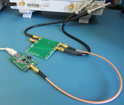
| First Test Setup with Crosstalk PCB and Pulse Generator |
For validation, measurements were taken using an oscilloscope with a bandwidth of less than 500 MHz and a simple pulse generator (Microchip version) designed in a previous blog.
 |
| Pulse Generator Frequency |
 |
| Pulse Generator Rise Time |
With the pulse generator providing the 1.4 ns rising edge signal into the aggressor trace (CH2 blue trace), the connector at the near end of the victim trace (CH1 yellow trace) was connected to the oscilloscope.
 |
| Near End Crosstalk PCB Measurements |
For a second measurement, the two ends of the victim trace were connected to oscilloscope. When the pulse was applied to the aggressor, the signal entering and then reflecting (near and far end) was measurable.
 |
| Near and Far End Crosstalk PCB Measurements |
Summary
This short post introduced a printed circuit board for testing the behaviour of signals relating to crosstalk measurements. The option to use a series resistive element was included but not tested in this post.
The PCB Gerber files are downloadable using the link below for those who prefer to build the board and perform testing at home, school or in the lab. The Gerber files use the format as defined on this page.
 |
| Crosstalk PCB Gerber Files |
