Introduction
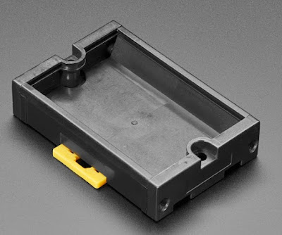
This microblog provides the dimensions and clearances required when a circuit board is used with an Adafruit DIN rail holder circuit board holder, part number 4435.
 |
Adafruit DIN Rail Board Holder (Courtesy Adafruit)
|
Circuit Board and Keep Out Dimensions
The dimensions provided in the Adafruit 4435 datasheet are precise for the circuit board shape however the information does not include any other clearances. For component placement on the circuit board, an area of 46.6 mm x 70 mm is available. The rails that hold the circuit board consume some board space.
The purple line shown inside the object below (Keep Out Area) shows the area that can be used for components or hardware.
 |
Adafruit (4435) Circuit Board Dimensions and Usable Board Area
|
The distance between the bottom side of the example circuit board and the DIN rail holder is approximately 8 mm (assuming a 1.6 mm board). The separation between the faces is closer to 8.5 mm although factors such as thermal expansion and circuit board warping should be taken into account.
 |
| Adafruit (4435) Printed Example Circuit Board Showing Clearance to Case |
Keep Out Area Validation
In each corner of a example circuit board, at the edge of the keep-out region, an extruded feature was placed.
 |
Circuit Board Positioning Feature
|
A 3D model of the circuit board was printed. For validation testing, this circuit board was fit into the Adafruit DIN rail holder. Using a feature on the printed model allows easy checking of tolerances, especially between horizontal and vertical faces.
 |
Example 3D Printed Circuit Board in Adafruit DIN Holder (4435)
|
Downloads
The files and models provided below are without the raised feature mentioned in this blog.


