Showing posts with label holder. Show all posts

Saturday, 31 January 2026

Model Rocket Engine Test Stands

 Introduction 
This blog provides ideas and an example for 3D-printed metal rocket test stands designed to accommodate the popular Estes-sized model rocket engines.

Rocket Engine Holders

Why an Engine Test Stand?
To conduct rocket engine tests and measurements, a model rocket engine test stand was required. The stand was designed to serve as a motor anchor and mount on the horizontal axis. Since pricing from 3D metal printing companies has become more cost-effective, two stand designs were tried. Cost-reducing changes were implemented in the first revision test stands with a focus on reducing the printed weight.

Development and Manufacture
Autodesk’s tool, Fusion 360, was used in the development of the rocket engine holders. JLC3DP performed the 3D printing in stainless steel (BJ-316L). 

What Changes?
Since 3D printing can be charged by weight (or volume), and because the thrust axis of the rocket engine is well established, the side walls of the rocket engine stand were partially excluded. The exclusion (cutout) in the stand body, as depicted in the images below, reduced the weight by approximately half. Additional changes could be made to reduce the weight if the focus were on cost-effectiveness, and with that in mind, the CAD files are provided at the end of this post for download.

3D Printed Test Stand
The first test stand was a simple prototype for Estes A-C engines. Some engines did not fit entirely into the 3D-printed metal holder, while others were easily inserted. This was because there are variations in the diameter of rocket engines, and older engines may have expanded with age.

Model of Model Rocket D Engine Holder

Model of Model Rocket C Engine Holder

Some videos below show how the motor was mounted. As a side note, the exhaust temperature was measured at almost 600 C, 100 mm from the engine nozzle.


Downloads

Files are exported from Fusion 360.

Fusion 360 C Engine Holder Model

C Engine STL File

The D engine holder model below has a 0.5 mm larger bore than the model in the above videos.

Fusion 360 D Engine Holder Model

D Engine STL File


Sunday, 26 September 2021

Soldering Iron Tip Holder (3D Printed)

Summary
This short post provides the file for a 3D printable version of the tooltip holder created in a previous post.

3D Printed Soldering Iron Tip Holder

Details
The file in the Downloads section below is a close representation of the wooden tool tip holder. Fusion 360 was used to draw the model; available on request.

Soldering Iron Tip Folder Model

Verification of the model was performed by converting to GCode and printing on a 3D Printer (Ender 3) using PLA with a 10 % fill, no bed adhesion and default wall and base thickness. The printed dead weight of the tooltip holder may be too light for some users; an additional weight on the base may be required.

Downloads 

Soldering Iron Tooltip Holder (STL)

Sunday, 29 August 2021

Soldering Iron Tip Holder

Summary
This blog covers the build of a soldering iron tip holder using demolition site lumber.

Soldering Iron Tip Holder


Build Process
For the build, a piece of lumber (Jarrah) was salvaged from demolition scrap several months ago.

Demolition Site Salvaged Lumber

Without access to a lathe to create the required shape, a 64 mm diameter hole saw was utilised to create the round shape of the holder. The hole saw was drilled from opposing sides of the lumber to achieve the necessary depth.

Holder Cut by Hole Saw

Sanding of the holder was performed with 120 Grit on a belt sander then followed by 240 Grit on an orbital sander. The finished diameter of the holder was around 60 mm and the height was 72 mm.

Sanded Soldering Iron Holder Form

A paper template was printed to assist in locating and marking positions for the Hakko T-12 type soldering iron tips. The six positions could be increased to eight or ten without overcrowding.

Holder with Tip Position Template

Holes for the soldering iron tips were drilled with a 6 mm bit to a depth of 35 mm. The shaft diameter of T-12 tips is marginally larger than 5.5 mm.

The central hole created by the hole saw was glued and plugged with a wooden dowel.

Holder with Six Drilled Tip Positions

After the glue had cured, the dowel was finished flat with the surface of the holder. A 16 mm Forstner bit was drilled to a depth of 35 mm. The 16 mm diameter of thr bit suits Stannol PCB flux pens.

Holder with All Drilled Positions

All the holes were deburred with a 5 - 10 mm countersinking bit and the holder given a final sand.

Three coats of primer (
Rust-Oleum flat white Primer) were applied to the holder with sanding using Grade 000 steel wool between each coat. Rolled sandpaper was used for the drilled holes. 

Soldering Iron Tip Holder with First Coat of Primer
Holder with First Coat of Primer

For the final colour of the holder, Rust-Oleum Blue Diamond was chosen. The colour was applied in three coats with sanding using Grade 000 steel wool after the initial two coats. A fine bristle paintbrush was used to paint inside the holes.

Soldering Iron Tip Holder with Final Coat of Paint
Holder with Final Coat of Paint

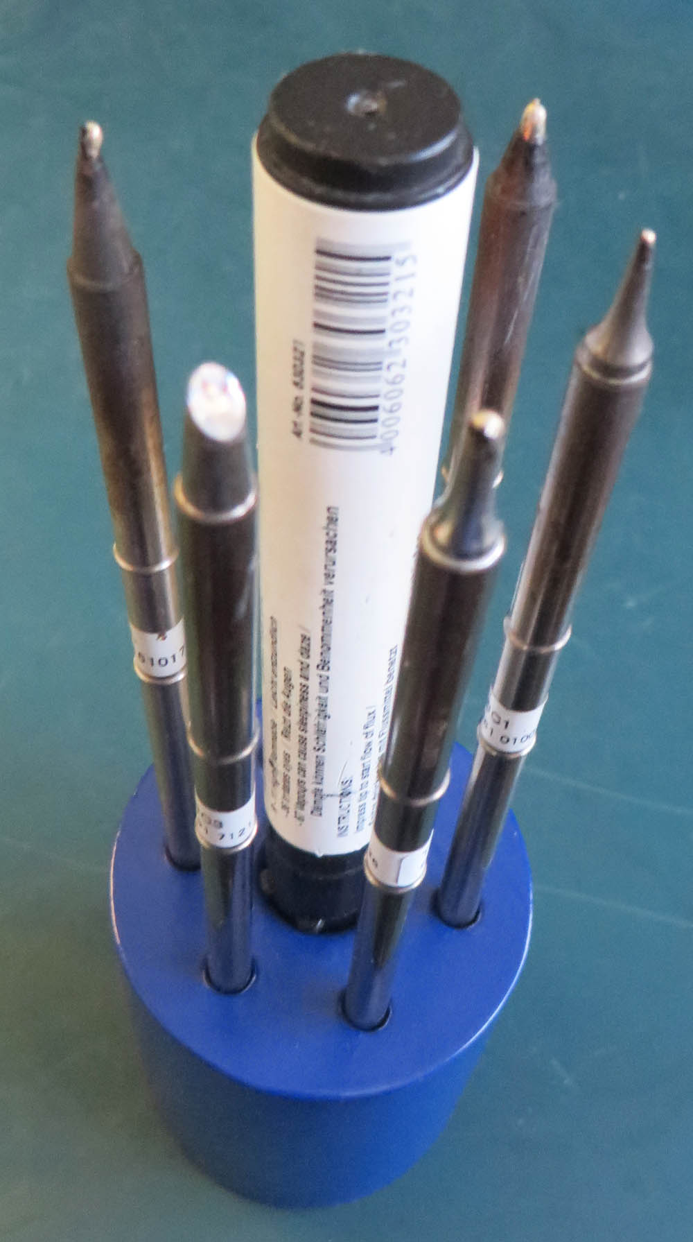
Shown below is the soldering iron tip holder with tips and flux pen mounted.

Soldering Iron Tip Holder with Tips and Flux Pen
Holder with Tips and Flux Pen
 
Summary

While the primer and colour spray paints achieved a descent finish, for longevity of the holder a harder two-pack or epoxy-based paint may be preferred.