Showing posts with label USB. Show all posts

Sunday, 9 June 2019

USB Large capacitance on data lines

Summary
This post details how the fitting of incorrect capacitors on USB lines can result in operational issues.

Hardware
After several years of use some of the surface mount capacitors on my FTDI branded debugger module showed signs of cracking, time to replace them.

FTDI VNC2 Debugger Module
Both capacitors (C8 & C9) associated with the USB D+ and D- lines were removed without any resulting communications issues. Schematic extract below was taken from the VNC2 Debugger datasheet.


FTDI VNC2 Debugger USB Input Section
As the USB line capacitors are there for multiple reasons, replacements were located. FTDI recommend capacitors in their Debugging Application Notes to prevent the reset of FTDI devices from spurious signals.

Wrongly Marked Components
The two USB line capacitors were replaced with what was presumed to be similar devices. Upon plugging the debugger into the computer an error message was displayed stating that the USB device could not be identified.

USB Signals
To diagnose further the oscilloscope was powered and the two USB signals probed.


USB Signals with Large Capacitors
The capture above shows the signals. Excessive rounding of the waveform usually indicates a high capacitance. 

Removing the new capacitors and verifying their capacitance confirmed that the value on the manufacturer packaging was incorrect.


USB Signals with Small Capacitors
With the capacitors removed the debugger began operating normally. Alternative replacement were fitted. The subsequent capture shown above is more indicative of USB signals.


Tuesday, 9 January 2018

Prolific USB To Serial Code 10 Windows 10 Networked

Summary
Windows device driver Code 10 issues, with legacy Prolific adaptors or counterfeit chips have been investigated by countless people, there however remains instances where many solutions fail to work. 

This blog contains a step by step guide which aims at addressing the Code 10 issue for Windows 10 networked installations (domain) and possibly earlier Windows versions, when current internet listed solutions or the newer Prolific driver 3.8.18.0 driver may not work.

From experience, either the newer Prolific driver for Windows 10 or the guide detailed in the blog, have resolved the issue on networked Windows 10 machines having the code 10.

Why Another Fix
The first reason for this fix relates to Windows 10 computers on a workplace network (domain) where software and driver updates are applied in a blanket roll out, when a newer driver version is available. This is an accepted process that facilitates software improvements however the process is troublesome when there are either driver or hardware related issues. This issue can be addressed by preventing the driver update of the specific USB device.

The second reason for this blog relates to online software fixes released with little or no explanation as to what software mechanisms are under the hood. Running an executable from an unknown website leaves me personally with an uneasy feeling. Installing some malevolent software on a home computer limits exposure to possibly a few computers. Installing the same software on a workplace network, with possibly dozens or more networked computers, is an entirely different matter.

Certainly there are noteworthy websites with documented / packaged fixes that can be tested if not done so already.

http://www.ifamilysoftware.com/news37.html

http://dronespersonalizados.blogspot.com.au/2014/03/pl2303-error-code-10-how-to-fix-windows.html

http://www.totalcardiagnostics.com/support/index.php?/Knowledgebase/Article/View/92

Description of the Fix
Fixing the driver issue (Code 10) can be achieved in four steps.

Step 1. With the Prolific USB adaptor fitted to the target computer, uninstall the Windows Prolific driver from Device Manager for that USB port.

Step 2. With the Prolific USB adaptor fitted in the same port, install the Prolific driver version applicable to the Prolific hardware used. This step may require some experimentation with earlier Prolific driver versions. Version 3.3.2.102 worked for both my Windows 10 installations. Prolific 3.3.2.102 compressed file here on Google drive. This driver is signed and should not be used otherwise.

Step 3. Repeat steps 1 and 2 for all USB ports on the computer, including any USB hubs or docking stations connected to the computer where the Prolific USB device may be connected.

Step 4. Change the local computer Windows Group Policy settings to prevent updates for only that Prolific USB device. For changes to be applied using the Group Policy Editor, the computer must be connected to the relevant Domain. The Group Policy can then updated to prevent Windows Updates for USB devices matching the Prolific USB VID and PID.

Process Explained
The image below is a capture of the Windows 10 Device Manager showing the yellow icon for the Prolific USB to Serial adaptor.


Device Manager Prolific USB to Serial - Code 10
Step 1.
With the Prolific USB device installed, remove the Prolific driver by opening the Properties of the USB device shown in Device Manager.


Device Manager Prolific USB to Serial - Driver
Navigate to the Driver tab and click the Uninstall Device button.

Step 2.
Install the suitable Prolific driver for computer and operating system. For a Windows 10 installation on a laptop the Prolific driver version 3.3.2.102 was found to be suitable. This version may vary for other hardware types and Windows installations.
Device Manager Prolific USB to Serial - New Driver

Step 3. 
Repeat the process for each USB port associated with the computer.

On the example laptop used for this blog, using the Prolific USB device on a second USB port results in a new serial port enumeration as shown in the image below. 


Device Manager Prolific USB to Serial - Code 10
Again with the Prolific USB device installed, remove all newer Prolific drivers by opening the Properties of the USB device shown in Device Manager.


Device Manager Prolific USB to Serial - Driver
Navigate to the Driver tab and click the Uninstall Device button.


Device Manager Prolific USB to Serial - New Driver

Step 4.

With the computer connected to the computer Domain and the Prolific USB device still installed, open the Properties of the Prolific USB device shown in Device Manager.


Device Manager Prolific USB to Serial - Hardware ID
Navigate to the Details tab. 

From the Property drop down list box select the Hardware ID's item. As the information displayed will be used when configuring the Windows Group Policy this window can be left open.

From the Windows Start open the Group Policy Editor by typing gpedit.msc. If the installation is Windows 10 Home the Group Policy Editor will not be found - possibly disabled in Home editions. 


Windows 10 Group Policy Editor
With the Group Policy Editor open, navigate to the Administrative Templates folder, then System, then Device Installation.


Windows 10 Group Policy Editor  - Device Installation
Windows 10 Group Policy Editor  - Device Installation
Select the Device Installation Restrictions folder then in the Window pane to the right, double click the item Prevent installation of drivers that match any of these device ID's. A new window will be displayed.


Windows 10 Group Policy Editor  - Device Installation Restrictions
Windows 10 Group Policy Editor  - Device Installation Restrictions
Click the Enabled radio button in the top left of the window.


Windows 10 Group Policy Editor  - Device Installation Restrictions Enabled
Windows 10 Group Policy Editor  - Device Installation Restrictions Enabled
Click the Show button to configure the Prolific USB ID.


Windows 10 Group Policy Editor  - Device Installation Restrictions Empty ID
Windows 10 Group Policy Editor  - Device Installation Restrictions Empty ID
Switch back to Device Manager and copy the first entry from the Hardware ID.


Device Manager Prolific USB to Serial - Hardware ID

Paste this information into the Group Policy Editor. Repeat for process for the second line in Device Manager. The result should be similar to the image shown below.

Windows 10 Group Policy Editor  - Device Installation Restrictions Updated ID
Windows 10 Group Policy Editor  - Device Installation Restrictions Updated ID
Close all windows and restart the computer so that the Group Policy changes are applied.

Driver updates should no longer be applied to that specific USB device.

Note on Limitations - Updating Drivers
Should a similar Prolific or other 'grey' USB device with the same VID and PID require a driver change, then the Windows 10 Group Policy Editor  - Device Installation Restrictions must be changed to Not Configured or Disabled.

Attempting to update the driver, without disabling the installation restriction, will result in a window similar to the image shown below.


Device Manager Update Driver - Forbidden System Policy

Hope this fix helps!

Downloads
Prolific driver 3.3.2.102


Monday, 17 April 2017

Beta Layout V2 Controller RS232 to USB Upgrade

Summary
As mentioned in a prior blog involving the Beta Layout V2 Reflow Controller, the on-board RS232 can be removed and USB added using an adaptor such as the Adafruit - CP2104.


Beta Layout V2 with USB

Hardware Required
Beta Layout V2 Controller
Adafruit USB to TTL Adaptor #CP2104
1 x 1k 0805 resistor
2 x M2.5 plastic screws
2 x M3 x 15mm bolts
2 x M3 star washers
2 x M3 flat washers
2 x M3 nuts
1 x plastic L bracket (home made)
3 x small lengths of hookup wire

Opening the Controller
As detailed on a previous blog the Beta Layout case does not use fixing to hold the two part enclosure together. Instead there are a pair of opposing plastic clips on the lid and base, concealed by the ventilation holes, which were released using a flat blade screwdriver to gain access to the controller.

Beta Layout V2 Controller
There are only a handful of components associated with the existing TTL to RS232 driver (MAX232) and these components are all surface mount capacitors for the charge pump or supply decoupling. For more details on the RS232 driver see the Maxim datasheet MAX232.

In the image below the components to be removed are circled in RED.


Beta Layout V2 RS232 Driver
Logic Board RS232 Driver
To unsolder the MAX232 driver it was easier to unscrew the logic board so that the board could be worked on directly. While the 10 way header for the serial port can be unplugged, the Thermocouple wires are soldered directly to the logic board so the connector must be removed from the plastic panel.

To remove the Thermocouple connector from the panel of the unit, the bolt connected to the metal plate is first unscrewed, then the bolt holding the Thermocouple connector together is removed. This allows the connector to come apart allowing the logic board to be removed from the unit.


Thermocouple Connector Disassembly
Removing the RS232 Driver
One of the easiest methods to remove the MAX232 driver is to use two soldering irons, unless you have a tool for your soldering iron that can remove SOIC packages! Alternatively a set of side cutters to chop the legs off the driver and solder wick to clean up the mess works wonders if there is no interest in saving the driver.

Beta Layout Logic Board RS232 Driver Removed
Logic Board RS232 Driver Removed
In the image above the driver and four charge pump capacitors were removed. The capacitor to the lower left of the MAX232, for the power supply decoupling, was left on the PCB. For people choosing to use another flavour of USB to TTL adaptor they may find that external 5V power is required. This capacitor, even though small, may be able to provide some minimal power supply decoupling for an alternative adaptor board.

The Adafruit adaptor board which was used in this upgrade, is bus powered, so this decoupling capacitor is not used and could be removed. Below is an image of the changes to the logic board. These are explained below.

Logic Board with Adafruit USB Adaptor
Logic Board Changes
For the image above the changes listed below were made.
  1. Bridge the transmit lines on the MAX232 footprint.

    As shown in the image below there are two pins which need to be linked 'shorted' together. These pins are actually pin numbers 7 and 10 on the actual MAX232 transceiver.

    Bridge MAX232 Transmit Lines
    Bridge MAX232 Transmit Lines

  2. Connect a 1k resistor between the receiver lines on the MAX232 footprint.

    Since the receiver line from the USB to TTL converter can provide enough power to supply the ATMEGA a current limiting resistor was added between the boards. The rail to rail steering diodes inside the ATMEGA cause this phenomenon. See this EEVBlog #831 Episode for a detailed description on YouTube.

    Add 1K Resistor Receive Line
    Add 1K Resistor Receive Line
    The resistor is fitted between pin 12 of the MAX232 and the via directly adjacent to the right between the transceiver pads. As the board via's are untented the resistor can be soldered directly to the via.

  3. Connect TTL transmit, receive and 0VDC to the Adafruit adaptor.

    The original transmit and receive lines on the PCB header were reused for connection to the USB to TTL converter. As shown in the image below the three connections are all made to the inside pins on the header.

    USB to TTL Connections
    USB to TTL Connections
    The transmit connection is the TXD pin, receive the RXD pin and 0VDC is the GND pin on the Adafruit USB to TTL adaptor.

Mounting the Adafruit Board
To mount the Adafruit board a custom L bracket was made from plastic and fashioned to cover the old 9 pin serial connector cut out.


Adafruit USB to TTL L-Adaptor
Since there are only two mounting holes (ID 2.5mm) on the Adafruit board a pair of 2.5mm self-tappers were used to hold the board in position.

Mounted Adafruit Board
To hold the L-bracket in position against the panel of the Beta Layout unit, a pair of 3 x 15mm bolts were used with the usual star washers and nuts on the rear and M3 flats against the outside of the units panel.

Mounted Adafruit in Case
As a dry run the unit was assembled without fixing the power board down to check the clearances.

Final Mounting of USB to TTL Adaptor

Testing the Adafruit Board
To be prudent the USB was connected to a PC running TeraTerm. The unit was powered with the Thermocouple fitted into the connector.


USB to TTL Converter in Device Manager
Running on Windows 7 the drivers installed automatically for the Silicon Labs USB controller. Below is a capture of the USB connection running at 9600 baud.

TeraTerm - USB to Beta Layout V2
The USB to TTL adaptor was working as expected and so the Beta Layout unit was reassembled by fixing down the power board.

Power Board Fixings Under Connectors
Final Mounting 
Note that one of the plastic screws to hold down the power board was located underneath the mounted Thermocouple connector. The second screw was located on the opposite end of the power board underneath the Adafruit PCB. 

Should repairs need to be performed on the power board the Thermocouple connector and USB board would need to be removed to gain access to the unit.

Thursday, 5 November 2015

Beta Layout Reflow Controller with USB (FTDI FT311) connection to Android Phone

Summary
As a follow-on from the original Beta Layout post, this information shows one method of connecting the Beta Layout reflow controller serial interface, to an Android compatible phone with some off the shelf hardware.

Reflow Controller
The Beta Layout Reflow Controller (V2) provides a connection to it's inner workings through a serial port (RS232), 9 pin D type connector. While moving a laptop to the reflow controller every time the controller requires and adjustment, there are devices such as the FTDI USB specific hardware to suit interfaces with Android phones.

USB Development Module
One of these devices, FT311, is a plug and play USB Host chip for Android devices. There is an associated development module, UMFT311EV, that provides a number of interfaces, one being RS232. The header pinouts on the module suits off the shelf adaptor boards and some shields.


FTDI FT311 Dev Module

RS232 Adaptor
The FTDI board is TTL so an RS232 shield such as the model from DFRobot can be used to make the required conversion.

DFRobot RS232 Shield

While the 5V and 0V power header is pin compatible between the boards, the communications header with TX, RX, CTS and RTS requires a few jumpers.

Linking Interboard TTL
From Section 4.1.2 of the UMFT311EV datasheet the hardware connections are identified.


UART Hardware Pinouts

Since the hardware handshaking is not used these two pins 5 and 6, can be joined together for now.

DF Robot J1 Pinouts
DF Robot J1 Pinouts

The corresponding Tx and Rx connections as shown on the DF Robot shield schematic, follow the Arduino shield mapping and are available on pins 1 and 2.
To make the modifications, pins 1 and 2 on the Robot shield are snipped off or pulled to the side as not to mate with the FT311 development module.


DF Robot Jumper Connections

Using wire links or a pin header inserted into J1 on the Robot shield, pin 1 RXD is linked to pin 4 or RXD for the USB. Then pin 2 TXD is linked to pin 3 or TXD for the USB. Lastly pins 5 and 6, CTS and RTS are linked.


The FT311 module and Robot shield can be fitted together.

RS232 Cable
Since both the communications devices sport a 9 pin female D connector a null modem cable is required between them.

Hardware Assembly
The other two pieces of hardware required are a power supply or plug pack to suit the development module and the USB charging cable used with the Android phone.


Assembled FT311 and RS232 Shield Hardware

Android Terminal Program
To communicate with the Development board FTDI provide AOA HyperTerm, which is a basic terminal interface for the Android. Available on the Google Play Store and passes the Android MyPermissions and 360 Security checks.

With the HyperTerm application installed and the hardware setup powered then phone can be connected to the charging cable. In doing so the HyperTerm application is automatically launched.


AOA HyperTerm Application from FDTI


To configure the communications select the Settings button then choose the interface required. For the Beta Layout reflow controller, 9600, 8, N, 1 are the communications settings and since the hardware handshaking is looped at the DF Robot shield, the default settings in HyperTerm can be used.


AOA HyperTerm Communications Settings

After selecting Configure commands can be exchanged with the reflow controller.

AOA HyperTerm Communications Settings Confirmation

Starting with sending help and a CR the list of available commands is returned.

Beta Layout commands on AOA HyperTerm

In the screenshot above the help screen and status data is displayed in the HyperTerm window. The status information is configured for bursts at five second intervals which is used to track the starting and operational temperatures.

The final setup of the hardware as used on the bench is shown below. For similar and compatible Android USB hosts, shields or development kits the same process should be possible!

Beta Layout, USB Dev Kit, RS232 Shield with Android and AOA HyperTerm

Saturday, 30 May 2015

Arduino USB Host and SMTech DM620 with Datalogging

Summary
The requirement for this project is to use an Arduino (Atmel micro) to trigger the data logging feature on a digital multimeter (DMM).

For this project the DMM, SMTech DM620, is a device sold in Australia by the usual retail suspects such as Altronics - Q1198. There are a plethora of alternative low cost DMM's, less than AUD $150, with Bluetooth or wireless USB interfaces such as this device from Jaycar - QM1575 with would suit similar data logging applications.

In this project the Arduino will serve as a USB Host in order to control the functions on the DMM. There are always other solutions, especially with the latest DMM's which support Ethernet, however legacy equipment such as this DMM, can become an exciting challenge.

DMM620 Digital Multimeter with Logging

In the USA, companies such as CircuitSpecialists have sold this DMM in the past however it appears that the unit has become obsolete or is no longer available - http://www.circuitspecialists.com/dm620.html

Lets Begin...
Starting out the first step is to determine if the USB communications protocol between the DM620 and the corresponding PC software is open source (unlikely) or has already been dismantled by checking the many web hosted repositories such as CodeBender, GitHub and so on. Turns out lamentably not. 

Therefore the USB communications can be monitored using a software monitoring package such as USBTrace from SysNucleus http://www.sysnucleus.com/ or USBlyser of the same company - http://www.usblyzer.com/. The control codes can then be acquired and used to configure the DMM from the Arduino. Software of choice is installed and DMM hardware setup including USB cables fitted.

As with any new tool, in this instance USBTrace, it's valuable to become familiar with its features, quirks and operation.

USBTrace Screenshot
USBTrace screen shot

USBTrace has an easy to use tree structure interface, as shown in the screen shot above. By plugging and unplugging USB devices from the computer the tree updates along with brief description of attached device. This can be used to assist in identifying where the DMM is on the tree.

Across the top of the USBTrace window is the application toolbar for performing the important functions of Start, Stop Capture and Export.


USBTrace Toolbar
USBTrace Toolbar

After performing a few logs of USB devices, the logging USBTrace format is quite clear, so the DM620 software can be installed. The install files are available in the downloads section on the following websiteQ1198 


LoggerDMM Software screen shot

The installer will grace a Windows computer with the software - LoggerDMM.exe (software), a screenshot of the running application is shown above. Note that on the same website is a user guide to read through, although the software is relatively easy to use. For the purposes of this project only the data logger mode is required to log the DC voltage of solar panels across the day, however for completeness all the modes and ranges will be captured.

With the DMM software running, USB cable plugged into the DMM and computer, DMM powered the Link button in the PC software can be clicked to verify operation.


DMM620 Display (USB connected)

When a connection is established the DMM will indicate a connection in the top right hand corner of the DMM's display.

With USBTrace running and the Link button selected in the DMM software, clicking on various buttons in the software will show data exchanged on the USB. USBTrace shows this data as a bulk or interrupt type which are two of the four types of transfer. To get deeper into the USB protocol, some six hundred pages, the standard is available at USB.org - http://www.usb.org/developers/docs/  

Beginning with clicking the Link button ON the first packets can be observed.


USBTrace Capture of DMM620 Communications

Working from the top down of the software log the first Input/Output (IO) exchange is an output to the DMM. Selecting a line at a time, the buffer is displayed in the bottom section of the window in Hex and ASCII. For readability the window can be undocked and resized.


USBTrace Buffer Out Capture

Looking at the outgoing data as Hex the first character is 02, representing ASCII Start of Text. The data of interest is followed by an End of Text, 03. As a reference for ASCII codes see - http://ascii-table.com/ascii.php. The outgoing USB packet together with the question marks that appear at the end of the ASCII commands or functions, seems to indicate a request for the DMM's configuration.

Now selecting the first incoming line of data shows values of interest. These would appear to be the enumerations for the various commands or functions of the DMM.


USBTrace Buffer In Capture

Recording the logged ASCII values sent from the DMM software for each Function, Range of that function, Mode and so forth allows a function table to be built. 

The next USB packet out shows additional functions, this time the ASCII is capitalised indicating requests are made in this format.


USBTrace Buffer Out Capture

Clicking the next logged incoming data provides some meaningful information also. The reading of 0.40mV matches the current Relative Reference shown on the DMM display.


USBTrace Buffer In Capture

So the Link connect operation to the DMM has been recorded. Link disconnect and all the remaining DMM functions can be recorded using the same capture and interrogate method with USBTrace.

Command: Open Link to DMM
Upon opening a link the DMM software requests the current settings on the device:

     02 46 55 4E 3F 3F 2C 52 47 45 3F 3F 2C 4D 4F 44 3F 3F 2C 48 4C 44 3F 3F 2C 50 53 54 3F 3F 03

     STX FUN??,RGE??,MOD??,HLD??,PST?? ETX

Note that there are no spaces after the STX and before the ETX ASCII codes as shown above, this is added for readability throughout the blog. The comma separation between commands is correct.

At this stage its important to note that the commands are not completely understood. Comparing the three letter abbreviation sent between the software and the DMM against the software an educated guess can be taken, giving:

     FUN - Function

     RGE - Range
     MOD - Mode
     HLD - Hold
     PST - Paused

So in response the request for the current settings the DMM responds with:

     02 66 75 6E 30 30 2C 72 67 65 31 31 2C 6D 6F 64 30 32 2C 68 6C 64 30 30 2C 70 73 74 30 30 03

     STX fun00,rge11,mod02,hld00,p00 ETX

The second request from the software is:

     02 50 52 56 3F 3F 2C 50 53 54 3F 3F 03

     STX PRV??,PST?? ETX

In response the DMM sends:

     02 70 72 76 2D 20 20 30 2E 34 30 6D 56 64 63 03

     STX prv-  0.40mVdc ETX

So does this translate into what needs to be sent from the USB Host, certainly does, with some further prodding and poking.

Command: Changing DMM Modes
With an open Link to the DMM, each of the modes are selected and the outgoing MOD recorded giving:

     MOD00- Data Logger

     MOD01 - Record Mode
     MOD02 - Relative Mode
     MOD03 - Compare Mode
     MOD04 - Trend Plot

The DMM responds to the mode change with an acknowledge packet and also sends a second packet to read any applicable settings. The first response is a confirmation:

     02 06 03

     STX ACK ETX

The second packet sent from software to the DMM requests any additional data applicable to the mode that was selected. For the Datalogger this response is comprised of three parts:


     STX plv060,00000,09999 ETX

Looking at the ASCII there is the start and end of text wrapping the sample time, start and stop address. These settings can be seen when pressing the Set button of the DMM. The range of the settings are as follows:

     Sample Time: 1 - 999s
     Start Address: 00000 - 17000
     Stop Address: 00000 - 17000

For Record Mode there are no parameters to be configured. There is however the option to read the status of the Pause button.

     STX pst00 ETX

In the response shown above the Pause button is off, pst01 indicates that the Pause button has been activated.

Next is Relative Mode which contains a single setting as seen in the response below.

     STX prv-  0.00mVdc ETX

 The range of the settings are as follows:

     Reference: -4999.9V - 4999.9V

In the response shown above the prv represents the relative reference value in millivolts.

The Compare Mode allows two settings to be set, HI and LO limit.

     STX pcv 100.00mVdc, 100.00mVdc ETX

 The range of the settings are as follows:

     HI Limit: -4999.9V - 4999.9V
     LO Limit: -4999.9V - 4999.9V

In the example above the pcv DMM response shows the settings.

Lastly the Trend Mode contains three settings, a reference value, vertical axis in volts/div and the horizontal axis in seconds/div.


     STX ptv 100.00mVdc, 100.00mVdc,000 ETX

The range of the settings are as follows:

     Reference: -4999.9V - 4999.9V
     V/Div: -4999.9V - 4999.9V
     H/Div: 20S - 10Hr

In addition to the second packet request and responses, there additional buttons for some modes. Data logging for example, contains Start, Recal, Clear and Setup buttons on the DM620. These will be captured later on.

Command: Functions of the DMM
Onto the measurement type (function), which will be investigated while the DMM is in Relative Mode.

Requesting the DMM DV Volts (DCV) function from the software results in three requests by the software. The first is the setting of the Function from the software:


     STX FUN00 ETX

Reply from the DMM is:

     STX ACK ETX

The second packet is the Mode set:


     STX MOD01 ETX

Reply from the DMM is:

     STX ACK ETX

The last packet is the Pause button status:

     STX PST?? ETX

The reply from the DMM is the devices status, in this instance OFF:

     STX pst00 ETX

Repeating the operations above for the other functions on the DMM produces the list below:

     FUN00 - DC Volts
     FUN01 - AC Volts
     FUN02 - Ohms
     FUN03 - Beep (Continuity)
     FUN04 - Diode test
     FUN05 - Capacitance
     FUN06 - DC milliamps
     FUN07 - DC Amps
     FUN08 - AC milliamps
     FUN09 - AC Amps
     FUN10 - Frequency
     FUN11 - Period
     FUN12 - Duty
     FUN13 - Temperature

In addition, any other request and reply packets are captured for each of the functions listed above.

There are now a number of request and reply packets that can be formatted into more meaningful data. This can assist when writing code. To start, the packet requests and replies exchanged between the software and the DMM are separated into individual requests and replies. The request and sets commands for Mode and Function are shown below.


DMM620 Mode Commands

DMM620 Function Commands

DMM Acknowledge
DMM Acknowledge

Continuing with the protocol there are several additional commands including the hold, function buttons, DMM date, time and termination of the link between the DMM and software.

Command: Close Link to DMM


USB Host Terminate Link Command

Termination of the USB connection, using the GTL command from the DMM software, is similar to the other commands previously listed in that the DMM will send an acknowledge command.

It is also important to note that the DMM software is programmed to send the correct combination of commands meaning a negative acknowledge is never seen in the messages. The NACK should be tested for and trapped in the software if it is used by the DMM.

Arduino Uno with USB Host
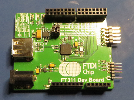
Instead of developing a PCB for this once off task, the USB interface can be realised with off the shelf hardware. For this project an Arduino Uno and a Sparkfun USB Host shield can be coupled with ready to go software.

Arduino Uno with USB Host Shield

Pictured above is the Sparkfun USB Host shield plugged into the Uno with the obligatory Pin 7 Reset Input linked to the Reset line. This link is required to drive the reset input on the 74HC4050.

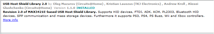
There are a number of USB Host shields such as the boards from Oleg Mazurov from Circuits@Home. Thanks to Oleg for the new revision 2.0 of the USB host library, this will be used along with the latest Arduino 1.6.5 software. By using the Arduino Library Manager, the USB Host library can easily be downloaded and installed into the Arduino software.

Arduino USB Host Shield Library

DM620 USB Device Manager Details
Before connecting the DM620 to the host shield, select the DM620 in Device Manager, Human Interface Devices (HID) on the PC. By using the Properties, Details buttons and then selecting Hardware ID's from the drop down list box some basic information for the DM620 can be collected. This information, Vendor ID (VID) and Product ID (PID) can be used to verify the USB Host shield connection.

DM620 in Device Manager, Details, Hardware ID's

DM620 Arduino USB Details
After the USB Host Shield is installed, there are a number of example sketches to choose from. In order to verify the USB VID and PID, the sketch USB_desc under the USB Host Shield Library 2.0 examples can be used.

Arduino sketch with USB_desc

The sketch is compiled, DM620 is connected to the USB shield and the program run.

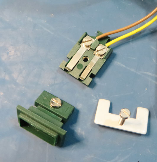
DM620 to USB Host Shield

From the Arduino terminal the relevant information, PID and VID, are shown at the top of the window. Device identification through USB communication appears to be running therefore some initial test code can be implemented.

Arduino Terminal Window

Due to a number of reasons this post was stopped, hopefully some of the information can be useful to anyone attempting a similar interface.