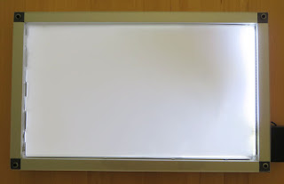
This blog illustrates how the salvaged LCD backlight from a BenQ model GL2430 monitor could be used in the design of a light table.
 |
| GL2430-B BenQ Monitor |
Just Another Light Table
Online suppliers such as Amazon have amazing light tables at prices which would force one to question why salvaged electronics should be used. In reply, this is a blog relates to salvaging, reusing electronic waste and my requirement was for dual purpose light table, home and workshop - this meant a robust and repairable solution.
LED Driver
In a previous blog relating to the salvaging of parts from a BenQ monitor, the LED driver and backlight were confirmed operational before starting the salvaging operation.
Further bench testing was needed to determine how the LED controller could be reused. At the core of the controller board sits a Monolithic Power System LED controller - MP3389. After perusing the datasheet a section on dimming on page 9 caught my interest.
This section of the MP3389 datasheet describes dimming control using a PWM signal or a DC signal. Dimming was not an immediate requirement for this project, although it was advantageous to know if such a feature could be added if required.
MP3389 DC Dimming Control
Further on page 13 of the MP3389 datasheet is a figure displaying the DBRT (Brightness Control) input. In order to use dimming with an external DC input voltage, a capacitor must be connected to the BOSC (Dimming Repetition Set) pin.
Checking the LED controller PCB it was apparent there was a resistor, R801, connected to the BOSC pin. This resistor was replaced with a small ceramic capacitor 0.033uF to set the required frequency.
The MP3389 datasheets lists the minimum operating voltage for the device as 5VDC. After the power connections were determine from the old BenQ loom, a benchtop power supply was set to 5VDC with a 500mA current limit.
With the power supply limited to 500mA the intensity of the backlight was comfortable to look at in a room with fluorescent lights. Full current was close to 1.2A at 5V DC. With a variable resistor attached to the BRBT pin, the dimming voltage to the DRBT pin of the MP3389 was adjusted until the power supply indicated around 480mA.
Control PCB Mounting
By some odd chance the controller fit neatly into a plastic enclosure. This was a UB5 plastic enclosure from a local supplier.
The variable resistor was measured between wiper and external terminals. This converted the variable resistor into two fixed resistors, 68k and 22k. As seen in the image below, the larger value resistor connected between the 5V supply and the dimming pin. The smaller value resistor connected between the dimming pin and supply 0V.
A chassis mount DC jack was added to one side of the enclosure away from the PCB. Also a small slot was added for the loom and connector which attaches to the backlight assembly.
Frame Construction
An aluminium lipped tube was used for the construction of the frame. The lip was used to retain the backlight.
To connect the frame together, plastic corner pieces were utilised.
The aluminium tube was cut into four pieces. Two at 555mm and the other at 325mm. A circular saw made light work of the tube.
Fitting the plastic tube corners was achieved with an engineer's square to check for square and a rubber mallet to massage the aluminium frame over the tube corners.
The remaining frame parts were assembled.
A cut-out was required for the cable assembly which connected between the backlight controller and backlight. An area on the frame was marked out then removed with a Dremel.
Control PCB
Two self-tapping screws were used to mount the control PCB enclosure to the aluminium frame.
For the connections to the control PCB, the original cable from the BenQ monitor was reused. The red, orange and green wires were connected to the 5V centre pin of the DC jack. These were the main supply and enable pins to the MP3389. The brown and black were connected to 0V of the DC jack. The white wire dimming connection was left floating and terminated in heatshrink.
To complete the control PCB assembly the cable to the backlight was plugged into the controller and the plastic lid attached.
The exposed backlight cable was to be protected with flexible plastic trunking.
USB Power Lead
The current limit set by the dimming resistors on the control PCB was less than 500mA. This value allowed off the shelf USB chargers or USB ports to power the light table.
A standard USB cable was modified so that only the USB power connected to the centre of the DC jack and the black to the outside of the jack.
Acrylic Cover Sheet
A removable acrylic cover, 3mm thick, was cut out to cover the backlight. Having a removable cover sheet was necessary with the light table being used around home and in the workshop.
Securing the Backlight
To secure the backlight into the frame, a bead of silicon was used between the four corners of the frame and the backlight body.
Acrylic Mounting and Feet
Four self-tapping screws and Nylon washers were used to secure the acrylic sheet.
On the rear side of the light table, four rubber feet were added to each corner.
Backlight Diffuser
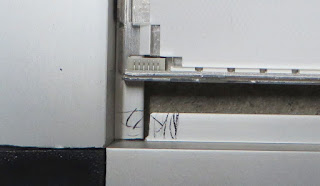
Using only the backlight diffuser which appears to be a type of translucent plastic film produces good uniformity. There were other optical sheets layered on the front of the original LCD although these were not used.
During cleaning of the acrylic with a dry cloth, the backlight diffuser became attracted to the acrylic and lifted off the backlight. An application of silicon helped reduce the lift of the backlight.
Online suppliers such as Amazon have amazing light tables at prices which would force one to question why salvaged electronics should be used. In reply, this is a blog relates to salvaging, reusing electronic waste and my requirement was for dual purpose light table, home and workshop - this meant a robust and repairable solution.
LED Driver
In a previous blog relating to the salvaging of parts from a BenQ monitor, the LED driver and backlight were confirmed operational before starting the salvaging operation.
Further bench testing was needed to determine how the LED controller could be reused. At the core of the controller board sits a Monolithic Power System LED controller - MP3389. After perusing the datasheet a section on dimming on page 9 caught my interest.
 |
| MP3389 Typical Application (Courtesy Monolithic Power Systems) |
This section of the MP3389 datasheet describes dimming control using a PWM signal or a DC signal. Dimming was not an immediate requirement for this project, although it was advantageous to know if such a feature could be added if required.
MP3389 DC Dimming Control
Further on page 13 of the MP3389 datasheet is a figure displaying the DBRT (Brightness Control) input. In order to use dimming with an external DC input voltage, a capacitor must be connected to the BOSC (Dimming Repetition Set) pin.
 |
| MP3389 Dimming (Courtesy Monolithic Power Systems) |
 |
| MP3389 LED Controller Change R801 to Capacitor |
 |
| BenQ Controller and Backlight |
Control PCB Mounting
By some odd chance the controller fit neatly into a plastic enclosure. This was a UB5 plastic enclosure from a local supplier.
 |
| Boxed MP3389 Controller |
 |
| Boxed and Modified MP3389 Controller |
Frame Construction
An aluminium lipped tube was used for the construction of the frame. The lip was used to retain the backlight.
 |
| Lipped Aluminium Tube |
 |
| Tube Corners |
 |
| Cut Aluminium Tube |
 |
| Aluminium Tube Corners Fitted |
 |
| Aluminium Frame Assembled |
 |
| Aluminium Frame Backlight Connector Markup |
 |
| Aluminium Frame Backlight Connector Cutout |
Two self-tapping screws were used to mount the control PCB enclosure to the aluminium frame.
 |
| Control PCB Enclosure Mounted to Aluminium Frame |
To complete the control PCB assembly the cable to the backlight was plugged into the controller and the plastic lid attached.
 |
| Mounted Control PCB Enclosure |
USB Power Lead
The current limit set by the dimming resistors on the control PCB was less than 500mA. This value allowed off the shelf USB chargers or USB ports to power the light table.
A standard USB cable was modified so that only the USB power connected to the centre of the DC jack and the black to the outside of the jack.
 |
| USB Power Lead for Light Table |
A removable acrylic cover, 3mm thick, was cut out to cover the backlight. Having a removable cover sheet was necessary with the light table being used around home and in the workshop.
 |
| Acrylic Cover for Light Table |
To secure the backlight into the frame, a bead of silicon was used between the four corners of the frame and the backlight body.
 |
| Fixing LED Backlight |
Four self-tapping screws and Nylon washers were used to secure the acrylic sheet.
 |
| Securing the Acrylic Cover |
 |
| Rubber Feet or Light Table |
Using only the backlight diffuser which appears to be a type of translucent plastic film produces good uniformity. There were other optical sheets layered on the front of the original LCD although these were not used.
 |
| Light Table Test |
