Showing posts with label LED. Show all posts

Sunday, 26 March 2023

Maker LED Flasher

Introduction
This blog details a prototype flasher circuit board for a school Maker community. The board design is built to accommodate through-hole and surface mount components. Featuring two component mounting styles allows the board to serve multiple uses in a school environment.

Dual LED Flasher PCB

Circuit
The circuit in the blog uses a well-worn astable LED flasher design made with discrete components. A transistor pair, wired in a common emitter configuration that drives a total of four LEDs were used. As a DC 9 V battery powers the circuit, more LEDs could be added to the design to interest young Makers.


LED Flasher Circuit
LED Flasher Circuit

For the feasibility review of the prototype by the Maker community, both circuits were placed on one side of the circuit board. A single switch (surface mount) was used to control power to the through-hole and surface mount sections.

PCB
An ABS enclosure from a local supplier was initially chosen for the prototype. PCB dimensions and the mounting hole locations for the circuit board were extracted from the ABS enclosure.

Components for the flasher circuits were placed on the top layer of the board. The battery connector was relegated to the bottom layer allowing a battery to be placed inside the ABS enclosure. Routing of the board used two copper layers.

Dual LED Flasher Routed PCB

3D Printed Case
With many Makers communities having 3D printers a printed enclosure was created based on the commercially available product
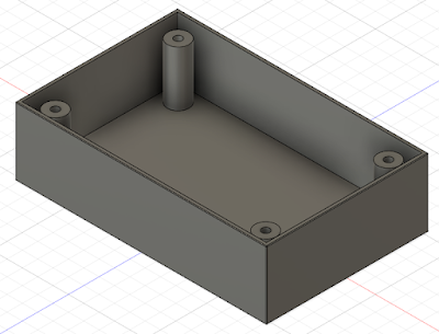
3D Model of Plastic Case

The Fusion 360 and STL files are located at the end of this post.
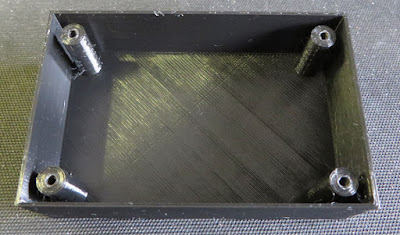
3D Printed Plastic Case

Making
The image below shows the through-hole portion of the circuit board after being populated and partly soldered by a school student. 

Half Populated LED Flasher Board

All the through-hole LEDs and capacitors were taken from salvaged components.

To hold the circuit board in position, round head metal self-tapping screws, 3 mm between crests, 7.5 mm in length were utilised.

The surface mount portion of the board was hand populated as a second step for this blog as can be seen in the image below.

Fully Loaded Flasher PCB in 3D Printed Plastic Case

The video below shows the through hole portion of the flasher board operating.


The second image shows the surface mount section in operation during testing.


Captures from Circuit
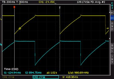
For those Maker communities interested in checking the circuit waveforms with a oscilloscope, below are some captures taken from the transistor collector and base connections.

Voltage Measured at Transistor Collector

Voltage Measured at Transistor Base

Summary
The LED flasher detailed in this blog was published as an example for Maker communities. Available for download below is the artwork for the circuit board and the file for a suitable 3D-printed case.

Flasher Schematic


Flasher PCB

Flasher Gerber

Flasher PCB Bill of Materials

3D Case in Fusion 360

3D Case as STL*

* If the plastic case is used, 4 x round head metal self-tapping screws, 3 mm between crests, 7.5 mm long may be required.


Sunday, 27 June 2021

Failing B22 E27 LED Bulbs

Summary
This blog reviews E27 or B22 style LED bulbs and the heat produced during operation.

LED Bulbs
In many mains powered LED bulbs a non-isolated, AC to DC LED driver is central to the design. For some bulbs, the Printed Circuit Assembly (PCA) containing the LED driver is separate from the LEDs. The LED
Printed Circuit Board (PCB) is usually metal backed to assist in heat dissipation. Both the LEDs and driver assemblies generate heat however the majority of heat is generated by the LEDs. 

Failed LED Bulbs
After several LED bulbs failed
across a period of weeks whilst daytime temperatures were high, the bulbs were opened for investigation. A failed Surface Mount (SMT) LED on the PCA was easily identified by black dots. Other LED bulbs had failed controllers.

Single Failed LED (Black Dots)


LED Testing
The LED driver on the bulbs was identified from the manufacturer Bright Power Semiconductor. The manufacturer datasheet detailed the LED driver‘s
single string capability was 120 mA with a maximum string voltage of DC 72 V.

Based on the driver string voltage, current with the dimensions of the LED in the bulb, the LED manufacturer appeared to be Everlight however this is not substantiated.

Using the specifications of the Everlight LED as a reference; a forward voltage of 9.15 V and 100 mA maximum current, a single LED board was left on the board. The single LED was powered from a benchtop power supply and measurements were taken.

For a constant current of 100 mA, the forward voltage was approximately 9.1 V. Measuring the temperature of the single LED after 15 min showed the case temperature of the LED reached 85°C mounted against the metallised board.

Temperature of LED Case

The rear of the metallised board reached nearly 40°C in the open air. When installed in the bulb, the temperature of the metallised board is expected to be higher considering the enclosed space.

Temperature of LED Rear Side
 
Changing the power supply to constant voltage mode with a 125 mA current limit, several measurements were performed at different voltages. Temperature measurements were also performed with a 26°C ambient. The graphed results are illustrated below.

LED Temperature vs Forward Current

Summary
During the testing process in this blog, a maximum LED case temperature of 101°C was measured with an ambient of 26°C.

Highest LED Temperature

It should be noted that many LEDs will operate continuously with a junction temperature at or above 100°C. Manufacturer datasheets usually provide graphs showing luminous flux changes with temperature which help determine derating performance.

The derating of luminous flux versus temperature varies considerably between LED manufacturers.
For the LED described in the blog, which was suspected to be manufactured by Everlight, the maximum junction temperature was 115°C. The derating curve to 115°C is shown below.

Everlight Luminous Flux vs Temperature

Using the bench tests results from this blog, it would be anticipated that with all LEDs active and an ambient temperature over 40°C, the LED junction temperature would exceed the datasheet rating. 

LED Bulb Driver and LED PCA's Showing Heat Discolouration

Interestingly many over the shelf LED bulbs do not detail maximum operating temperatures on their packaging or datasheets. For the LED bulb described in this blog, the high generated temperature was likely a contributing factor to the reduced lifetime of the bulb.

Sunday, 28 February 2021

LED Downlight Repair LD-18000R

Summary
This blog details the repair of a downlight (Model LD-18000R) with the replacement of the LED chip and the creation of a new LED retaining clip.

Fault Symptoms
Following several days of flickering, the LED in the downlight failed. Only a portion of the full light output was produced. Shown below is the downlight fully powered.

LED Downlight Failure - Low Output

Downlight Disassembly
With the LED disconnected from the LED driver, the rear plastic plate of the LED was opened to allow access to the cabling.

LED Downlight Rear Plate Fitted

LED Downlight Rear Plate Removed

The two screws allowing pivoting of the downlight in the base were removed. This step was not an essential step for repair as the metal retaining ring was screwed directly onto the aluminium heatsink.

LED Downlight Base Removed

The retaining ring was unscrewed from the aluminium heatsink to access the reflector.

LED Downlight Reflector in Heatsink
LED Downlight Reflector in Heastink

The reflector was set in place with a small amount of clear silicone. Using gentle prying the reflector was removed without damage.

LED Downlight Reflector

While inspecting the LED fitted to the heatsink, a crack in the plastic retaining clip was noticed. It was not known if equal pressure was applied LED. The capture below shows a hairline crack in the plastic near the top left countersunk screw hole.

LED Retaining Clip - Cracked

Replacement LED
To verify failure of the LED, the LED was powered using a benchtop power supply with approximately DC 32 V. Only a portion of the LED is illuminated in the capture below.

Damaged CREE LED
Damaged CREE LED

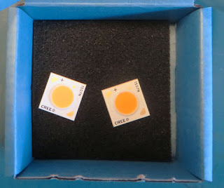
The 36 V Cree LED was marked as a CXA1507N which specifications of a colour temperature near 5000K (cool). Replacement CREE LED’s with a 3000K (warm) temperature were selected due to availability.

Replacement CREE LED's

Repairing the plastic LED retaining clip was an option however for longevity a new holder was created using a spare Printed Circuit Board (PCB). For the board used in this blog, the PCB was 1.6 mm thick, FR4 with a temperature grade (TG) 140 Celsius.

LED Retaining Clip on PCB

The outline of the plastic retaining clip was traced with a permanent marker onto the PCB.

LED Retaining Clip Tracing on PCB

Below is the PCB, drilled and shaped then placed against the CREE LED for verification.

Shaped Replacement LED Retaining Clip

Due to the PCB sitting physically higher than the previous plastic clip, new longer self-tapping screws were required. The longer screws would hold the PCB and LED to the aluminium heatsink. 

The replacement self-tapping screws were slightly larger than the previous screws meaning these needed to be cut into the aluminium block.

New Self Tappers for LED Heatsink

 
Isopropyl alcohol was used to remove the old heatsink paste and aluminium swarf. 

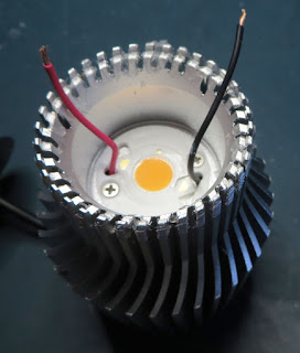
The positive and negative connections were soldered to the CREE LED. New heatsink paste was then applied lavishly to the rear of the LED.

Replacement CREE LED with Heatsink Paste

The replacement LED holder was deburred, cleaned, fitted then screwed down to the heatsink.

CREE LED with Replacement LED Holder

A brief power-up test was made to ensure the operation of the LED before reassembly.

Replacement CREE LED Test
  

Reassembly
For reassembly of the downlight, the plastic cover was fitted back to the aluminium heatsink.

LED Downlight Rear Plate Replaced

New white silicone was applied around the edge of the heatsink before the reflector was fitted.

Threaded LED Aluminium Heatsink

The base and retaining ring were assembled then the aluminium heatsink screwed into the ring.

Reassembled LED Downlight

As a final verification of operability, the LED was connected to the LED driver for testing.

Final Thoughts
The cost to replace each CREE LED in the set was less than USD 5.

For the faulty downlight, workshop time was required to create a replacement LED holder. Similar downlights did not have damaged LED holders.
 

Second CREE Downlight

Taking into account the cost of the LED and workshop materials, the repair cost was less than a new downlight. Furthermore, because the downlights were less than three years old, replacement of the LED’s appeared a reasonable investment. 

If the downlights were several years old, purchasing the replacement LED’s may become an issue. The remaining life of the LED driver would also need to be considered carefully before performing the repair.

Saturday, 23 February 2019

Light Table using BenQ GL2430 Backlight

Summary
This blog illustrates how the salvaged LCD backlight from a BenQ model GL2430 monitor could be used in the design of a light table. 


GL2430-B  BenQ Monitor
GL2430-B BenQ Monitor
Just Another Light Table
Online suppliers such as Amazon have amazing light tables at prices which would force one to question why salvaged electronics should be used. In reply, this is a blog relates to salvaging, reusing electronic waste and my requirement was for dual purpose light table, home and workshop - this meant a robust and repairable solution.

LED Driver
In a previous blog relating to the salvaging of parts from a BenQ monitor, the LED driver and backlight were confirmed operational before starting the salvaging operation.

Further bench testing was needed to determine how the LED controller could be reused. At the core of the controller board sits a Monolithic Power System LED controller - MP3389. After perusing the datasheet a section on dimming on page 9 caught my interest.


MP3389 Typical Application
MP3389 Typical Application (Courtesy Monolithic Power Systems)

This section of the MP3389 datasheet describes dimming control using a PWM signal or a DC signal. Dimming was not an immediate requirement for this project, although it was advantageous to know if such a feature could be added if required.

MP3389 DC Dimming Control
Further on page 13 of the MP3389 datasheet is a figure displaying the DBRT (Brightness Control) input. In order to use dimming with an external DC input voltage, a capacitor must be connected to the BOSC (Dimming Repetition Set) pin.


MP3389 Dimming
MP3389 Dimming (Courtesy Monolithic Power Systems)
Checking the LED controller PCB it was apparent there was a resistor, R801, connected to the BOSC pin. This resistor was replaced with a small ceramic capacitor 0.033uF to set the required frequency.


MP3389 LED Controller Change R801 to Capacitor
The MP3389 datasheets lists the minimum operating voltage for the device as 5VDC. After the power connections were determine from the old BenQ loom, a benchtop power supply was set to 5VDC with a 500mA current limit.


BenQ Controller and Backlight
With the power supply limited to 500mA the intensity of the backlight was comfortable to look at in a room with fluorescent lights. Full current was close to 1.2A at 5V DC. With a variable resistor attached to the BRBT pin, the dimming voltage to the DRBT pin of the MP3389 was adjusted until the power supply indicated around 480mA.

Control PCB Mounting
By some odd chance the controller fit neatly into a plastic enclosure. This was a UB5 plastic enclosure from a local supplier.


Boxed MP3389 Controller
The variable resistor was measured between wiper and external terminals. This converted the variable resistor into two fixed resistors, 68k and 22k. As seen in the image below, the larger value resistor connected between the 5V supply and the dimming pin. The smaller value resistor connected between the dimming pin and supply 0V.


Boxed and Modified MP3389 Controller
A chassis mount DC jack was added to one side of the enclosure away from the PCB. Also a small slot was added for the loom and connector which attaches to the backlight assembly.

Frame Construction
An aluminium lipped tube was used for the construction of the frame. The lip was used to retain the backlight.


Lipped Aluminium Tube
To connect the frame together, plastic corner pieces were utilised.


Tube Corners
Tube Corners
The aluminium tube was cut into four pieces. Two at 555mm and the other at 325mm. A circular saw made light work of the tube.


Cut Aluminium Tube
Cut Aluminium Tube
Fitting the plastic tube corners was achieved with an engineer's square to check for square and a rubber mallet to massage the aluminium frame over the tube corners.


Aluminium Tube Corners Fitted
The remaining frame parts were assembled.


Aluminium Frame Assembled
A cut-out was required for the cable assembly which connected between the backlight controller and backlight. An area on the frame was marked out then removed with a Dremel.


Aluminium Frame Backlight Connector Markup
Aluminium Frame Backlight Connector Cutout
Control PCB
Two self-tapping screws were used to mount the control PCB enclosure to the aluminium frame.


Control PCB Enclosure Mounted to Aluminium Frame
For the connections to the control PCB, the original cable from the BenQ monitor was reused. The red, orange and green wires were connected to the 5V centre pin of the DC jack. These were the main supply and enable pins to the MP3389. The brown and black were connected to 0V of the DC jack. The white wire dimming connection was left floating and terminated in heatshrink.

To complete the control PCB assembly the cable to the backlight was plugged into the controller and the plastic lid attached.


Mounted Control PCB Enclosure
The exposed backlight cable was to be protected with flexible plastic trunking. 

USB Power Lead
The current limit set by the dimming resistors on the control PCB was less than 500mA. This value allowed off the shelf USB chargers or USB ports to power the light table.

A standard USB cable was modified so that only the USB power connected to the centre of the DC jack and the black to the outside of the jack.


USB Power Lead for Light Table
Acrylic Cover Sheet
A removable acrylic cover, 3mm thick, was cut out to cover the backlight. Having a removable cover sheet was necessary with the light table being used around home and in the workshop. 


Acrylic Cover for Light Table
Securing the Backlight
To secure the backlight into the frame, a bead of silicon was used between the four corners of the frame and the backlight body.


Fixing LED Backlight
Acrylic Mounting and Feet
Four self-tapping screws and Nylon washers were used to secure the acrylic sheet.
Securing the Acrylic Cover
On the rear side of the light table, four rubber feet were added to each corner.


Rubber Feet or Light Table
Backlight Diffuser
Using only the backlight diffuser which appears to be a type of translucent plastic film produces good uniformity. There were other optical sheets layered on the front of the original LCD although these were not used.


Light Table Test
Light Table Test
During cleaning of the acrylic with a dry cloth, the backlight diffuser became attracted to the acrylic and lifted off the backlight. An application of silicon helped reduce the lift of the backlight.