Showing posts with label power. Show all posts

Sunday, 9 July 2023

Risinglink PD201W Power Failure Detector

Introduction
This blog provides a teardown of the Risinglink PD201W Power Failure Detector and wall plug adaptor.

Risinglink Module
Risinglink Module

Power Failure Detector Supplier
The power failure detector is branded with the logo of the company Risinglink. There are no product specifications for the detector on the Risinglink website but documentation is provided with the detector when purchased.

Package Contents
A mains wall plug (USA), USB cable and documentation are shipped with the power failure detector shipment.
Opening the Detector
A thin flat bladed screwdriver was used to release the lid from the case. The joint near the R and K in the Risinglink logo was the optimum lid leverage position. The plastic lid has two clips to retain the lid in the housing.
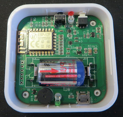
Risinglink Module Internal

The ESP-12F WiFi module, CR2 battery, buzzer, switches and LEDs are immediately visible on the circuit board upon opening the unit. Removing the circuit board was possible by pressing the green LED away from the edge of the case. There are no components on the bottom side of the circuit board.
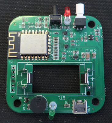
Risinglink Circuit Board


The battery manufacturer’s website (Tenergy) shows that the battery cell has a capacity of 800 mAh (Lithium). 

According to the ESP datasheet, operating the WiFi at continuous transmission draws an average of 71 mA. This would theoretically mean that a fully charged battery could monitor the status of the mains for hours.

As detailed in the documentation shipped with the detector, the white switch powers the detector with visual feedback provided by the red LED.

The black pushbutton is used to change operating modes as required when configuring the detector.

For the USB connector, only the power connections are utilised for monitoring the mains. No USB communication is possible to the detector. USB power is indicated through the illumination of the green LED.


Email Details
Notification emails are sent with “via amazonses.com” in the address. Emails events are received on the initial start-up, when a power outage occurs or when power restoration is detected.

The device PowerDetector started. Below is the device status at 01/01/2023 12:00PM.

  • Power Status: ON
  • Battery: 100%
  • WiFi Signal: -51

As mentioned in the documentation, an email is sent after 24 hours if there is no communication with the module.

The device, ............, may be OFFLINE. No ping from the device within 24 hours. Please check WiFi connection, Internet service, etc. Please contact support@...... if any question.

Wall Plug
The wall plug (model HNT-H510) features an internal On-Bright controller responsible for the control aspect of generating DC 5V in either Constant Voltage (CV) or Constant Current (CC) mode. As the image from the wall below shows, the design is the usual compact solution.

Wall Plug Internals
Wall Plug Internals

ESP-12F
On the detector circuit board is an unpopulated 6-pin straight header (H1). Using the datasheet of the ESP-12F and a multimeter, the pinouts of the header were determined as displayed in the image below.
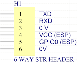
Pinouts for RisingLink Connector
Pinouts for Risinglink Connector

A TTL to USB converter was connected to the header pins Tx, Rx and 0 V. An oscilloscope was used to measure the transmitted UART data bit time which was approximately 13.3 ms or 75 bps during bootup. Data was shown however this was not reviewed in further detail. Programming information for the ESP can be found on dozens of sites, on example here.


Example data on boot.
ets Jan  8 2013,rst cause:4, boot mode:(3,7)
wdt reset
load 0x40100000, len 30596, room 16
tail 4
chksum 0x3e
load 0x3ffe8000, len 2004, room 4
tail 0
chksum 0xa1
load 0x3ffe87e0, len 4752, room 8
tail 8
chksum 0x6a
csum 0x6a


Modifying the Power LED
Situated on the side of the detector housing is a green LED. When a 5 VDC USB power adaptor is connected, the green LED bursts into operation. The brightness of the LED may be beneficial for a large factory but for a confined space, the LED brightness may benefit from a reduction.
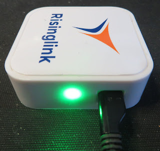
Bright LED on Risinglink Unit

The green LED uses a 1 k 0603 current limit resistor, R1. 

Resistor R1 on Risinglink Unit

To reduce the brightness of the LED, resistor R1 was increased to 10 k with the effects shown below. Resistor R1 was located between the green LED and the USB connector as shown in the capture above.

Dimmer LED on Risinglink Unit

 
Final Thoughts
The Risinglink PD201W is reasonably designed and simple to use. An option to use a custom email client over Amazon services would be preferable, especially for clients needing to security harden their network. 

Additionally, a helpful upgrade to the detector could be a battery-only access panel or a rechargeable battery.

Monday, 1 June 2020

Mikroe Buck 5 Click with PSoC5 VDAC

Summary
This post examines alternate means for driving the MikroElektronica Buck 5 Click hardware. First, the onboard digital Potentiometer was rewired in a new configuration and second the Potentiometer was replaced with Cypress PSoC.

Buck 5 Click - Courtesy MikroElektronica

Buck 5 Click with Digital Potentiometer and PSoC5
MikroElektronica's Buck 5 Click (MIKROE-3100) hardware presented itself as a cost-effective and off the shelf unit for testing the MAX17506 DC-DC Converter. The Buck 5 Click was designed primarily for use with other MikroElektronica hardware. The input voltage range of the Maxim buck converter (4.5V to 60 V DC) is not fully utilised on the Buck 5 Click (5V to 30 V DC). In the same manner, the output voltage appears capped at 20 V DC maximum. Even with the voltage limits the output range of the hardware was able to be tweaked. 


Wiring a Cypress CY8CKIT-059 prototyping kit to drive the Buck 5 Click required three connections for the SPI and two for power. The Buck 5 Click schematics indicated the board logic operated with 3.3 V DC however, the board was powered from 5 V DC. The supply range of the MAX5401 digital Potentiometer (pot) was 2.7 V to 5.5 V DC.

To control the digital pot, a PSoC Creator application using an SPI Master component was created


SPIM_WriteTxData(Buck5_Dig_Pot_Val);
while (0u == (SPIM_ReadTxStatus() & SPIM_STS_SPI_DONE)) 
{ }


The subsequent step of increasing the output voltage range of the Buck 5 Click was accomplished although the configuration of feedback resistor network (R8) and digital pot (U2) for the DC-DC converter (MAX17506) needed to switch places. The digital pot operating voltage was the reason for the change. The pot wiper was connected directly into the feedback pin of the MAX17506. Below is a working board with modifications.


Buck 5 Click Modified with Increased Output Range


The output voltage range of the modified board was approximately 4V to 18 V DC. The digital pot, with 255 positions, provided output voltage steps of 55 mV.

When applying power to the digital pot, the default setting is the middle position which may not be ideal in all instances. To control the behaviour of the buck regulator on power-up, a connection from the PSoC to the Enable line of the Buck 5 Click was used. A pull-up resistor (R4) was removed from the board to prevent the Buck 5 Click from starting when power was applied

Buck 5 Click with Cypress PSOC5 VADC, No Digital Potentiometer
Other solutions for adjusting the output voltage of a DC-DC converter, through control of the feedback pin, use external PWM or DAC sources.

The Cypress PSoC provides control of DC-DC converters either through PWM (Trim and Margin component) or a DAC (Current or Voltage component). This post used the PSoC VDAC8 component which provided 255 steps. For additional resolution the dithered VDAC component with 4096 steps could be used.

For calculating the output voltage for VDAC solution, Maxim published a notable tutorial deriving the output equation shown below from first principles.

VOUT = VREF(1 + (R1/R2)) + (VREF - VDAC) (R1/R3)                        Eq (1)

For connection of the VDAC to the feedback loop of the DC-DC Converter, one additional resistor (R3) was required.


DC-DC Converter Output Voltage Control Using a DAC

A spreadsheet was used to implement Equation (1) which allowed the three unknown resistor values to be manually changed and the output voltage range of the DC-DC converter observed.

DC-DC Converter Vout Spreadsheet Calculations

Equation (2) was used to ensure that the maximum current seen by the PSoC (DAC) was less than 25 mA.

i3 = (VREF - VDAC)/R3                       Eq. (2)

Quadrature Encoder
A quadrature encoder (Bourns PEC11R) was added to the design to allow for manual voltage adjustments. The QuadDec component was used to convert the encoder AB lines. The QuadDec returned value was limited to between 0 and 255. The reading from the QuadDec was then used to adjust the output of the VDAC component.


PSoC Creator Top Design
The project required the QuadDec, DAC and OpAmp components as shown below.


PSoC Creator Project Top Design


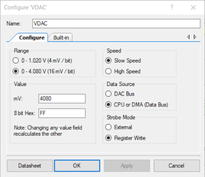
The calculations in Excel used a voltage range from 0.1 V to 4.08 V which was the option selected in the VDAC component.

VDAC Component Settings

While not essential, an OpAmp follower was added to the design.

OpAmp Component Settings

To maintain 255 positions the QuadDec component was changed from the default 8 bit to 16 bits.

QuadDec Component Settings

The remaining signals that are shown on the PSoC Creator project page (Top Design) were related to the DC-DC converter (PSU_Enable) and the on-board switch (Switch1). Voltage ramps were generated in code on start-up then Switch1 was pressed.

To facilitate testing of the encoder, a UART component was added to the project.

PSoC Creator Pin Mapping
Pin mapping for the design is shown below.


PSoC Project Pin Mapping


PSoC Creator Code
Listed below is an extract of some quick and grubby code used for testing the Mikroe with the PSoC Creator prototyping board.


/**
* @brief Main init and update VDAC based on quadrature encoder value
*/
int main()
{
  uint16_6 Encoder_Count, Encoder_Count_last = 0;
CyGlobalIntEnable();
QuadDec_Start();
UART_Start();
Opamp_Start();
VDAC_Start();
CyDelay(2000); /* Time to stabalise */
PSU_Enable_Write(true); /* Switch DC DC On */
pulse_on_switch1();
for(;;)
{
Encoder_Count = QuadDec_GetCounter();
if (Encoder_Count != Encoder_Count_Last)
{
if ((Encoder_Count <= MAX_ENC) && (Encoder_Count >= MIN_ENC))
{
write_to_uart(Encoder_Count);
VDAC_SetValue(Encoder_Count);
}
else if (Encoder_Count > MAX_ENC)
{
Encoder_Count = MAX_ENC;
QuadDec_SetCounter(MAX_ENC);
}
else if (Encoder_Count < MIN_ENC)
{
Encoder_Count = MIN_ENC;
QuadDec_SetCounter(MIN_ENC);
}
Encoder_Count_Last = Encoder_Count;
}
}
}

The functionality of the test code was to read the Quadrature Decoder, ensures the value read was within the range, then write the value to the VDAC.


Hardware Setup
Shown in the image below is the hardware setup which consisted of the Buck 5 Click, PSoC board and the rotary encoder.


Buck 5 Click with Increased Output and PSoC VDAC

Output Voltage Range and Regulation
The calculated output voltage range was for 1.62 V to 20.33 V DC and the measured range was 2.39 V to 20.42 V DC.

Rudimentary load tests were conducted with a resistive load driven by the Buck 5 Click. Tests indicated a 0.25 % voltage regulation with low loads (1W) and better than 0.1 % with higher loads (65 W). The DC-DC converter used in the Buck 5 Click (MAX17506) has a capability of 5 A. The full load current was not load tested.

Output Voltage Adjustment using PSoC
To change the output voltage of the DC-DC converter without the encoder, the value written to the VDAC was controlled in software. When the switch located on the Cypress CY8CKIT-059 prototyping kit was pressed on power-up, the code generated several pulse types.

Buck 5 Click Output Voltage Waveform from PSoC VDAC
Buck 5 Click Output Voltage Waveform driven from PSoC VDAC

The capture above shows the Buck 5 Click output voltage ramp up and down with a 220 R resistive load.

Final Thoughts
The MikroElektronica Buck 5 Click was a reliable hardware module which allowed a Cypress PSoC to be interfaced for testing. Using a DAC to adjust the output voltage provided an alternative method to the on-board Potentiometer. The option to use PWM control for voltage adjustment was not reviewed in this post although this method should be considered as another solution.


Downloads
PSoC Creator 4.3 Power Supply Project (PSU) Project.

PSoC Creator 4.3 PSU Project

Saturday, 23 February 2019

Light Table using BenQ GL2430 Backlight

Summary
This blog illustrates how the salvaged LCD backlight from a BenQ model GL2430 monitor could be used in the design of a light table. 


GL2430-B  BenQ Monitor
GL2430-B BenQ Monitor
Just Another Light Table
Online suppliers such as Amazon have amazing light tables at prices which would force one to question why salvaged electronics should be used. In reply, this is a blog relates to salvaging, reusing electronic waste and my requirement was for dual purpose light table, home and workshop - this meant a robust and repairable solution.

LED Driver
In a previous blog relating to the salvaging of parts from a BenQ monitor, the LED driver and backlight were confirmed operational before starting the salvaging operation.

Further bench testing was needed to determine how the LED controller could be reused. At the core of the controller board sits a Monolithic Power System LED controller - MP3389. After perusing the datasheet a section on dimming on page 9 caught my interest.


MP3389 Typical Application
MP3389 Typical Application (Courtesy Monolithic Power Systems)

This section of the MP3389 datasheet describes dimming control using a PWM signal or a DC signal. Dimming was not an immediate requirement for this project, although it was advantageous to know if such a feature could be added if required.

MP3389 DC Dimming Control
Further on page 13 of the MP3389 datasheet is a figure displaying the DBRT (Brightness Control) input. In order to use dimming with an external DC input voltage, a capacitor must be connected to the BOSC (Dimming Repetition Set) pin.


MP3389 Dimming
MP3389 Dimming (Courtesy Monolithic Power Systems)
Checking the LED controller PCB it was apparent there was a resistor, R801, connected to the BOSC pin. This resistor was replaced with a small ceramic capacitor 0.033uF to set the required frequency.


MP3389 LED Controller Change R801 to Capacitor
The MP3389 datasheets lists the minimum operating voltage for the device as 5VDC. After the power connections were determine from the old BenQ loom, a benchtop power supply was set to 5VDC with a 500mA current limit.


BenQ Controller and Backlight
With the power supply limited to 500mA the intensity of the backlight was comfortable to look at in a room with fluorescent lights. Full current was close to 1.2A at 5V DC. With a variable resistor attached to the BRBT pin, the dimming voltage to the DRBT pin of the MP3389 was adjusted until the power supply indicated around 480mA.

Control PCB Mounting
By some odd chance the controller fit neatly into a plastic enclosure. This was a UB5 plastic enclosure from a local supplier.


Boxed MP3389 Controller
The variable resistor was measured between wiper and external terminals. This converted the variable resistor into two fixed resistors, 68k and 22k. As seen in the image below, the larger value resistor connected between the 5V supply and the dimming pin. The smaller value resistor connected between the dimming pin and supply 0V.


Boxed and Modified MP3389 Controller
A chassis mount DC jack was added to one side of the enclosure away from the PCB. Also a small slot was added for the loom and connector which attaches to the backlight assembly.

Frame Construction
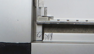
An aluminium lipped tube was used for the construction of the frame. The lip was used to retain the backlight.


Lipped Aluminium Tube
To connect the frame together, plastic corner pieces were utilised.


Tube Corners
Tube Corners
The aluminium tube was cut into four pieces. Two at 555mm and the other at 325mm. A circular saw made light work of the tube.


Cut Aluminium Tube
Cut Aluminium Tube
Fitting the plastic tube corners was achieved with an engineer's square to check for square and a rubber mallet to massage the aluminium frame over the tube corners.


Aluminium Tube Corners Fitted
The remaining frame parts were assembled.


Aluminium Frame Assembled
A cut-out was required for the cable assembly which connected between the backlight controller and backlight. An area on the frame was marked out then removed with a Dremel.


Aluminium Frame Backlight Connector Markup
Aluminium Frame Backlight Connector Cutout
Control PCB
Two self-tapping screws were used to mount the control PCB enclosure to the aluminium frame.


Control PCB Enclosure Mounted to Aluminium Frame
For the connections to the control PCB, the original cable from the BenQ monitor was reused. The red, orange and green wires were connected to the 5V centre pin of the DC jack. These were the main supply and enable pins to the MP3389. The brown and black were connected to 0V of the DC jack. The white wire dimming connection was left floating and terminated in heatshrink.

To complete the control PCB assembly the cable to the backlight was plugged into the controller and the plastic lid attached.


Mounted Control PCB Enclosure
The exposed backlight cable was to be protected with flexible plastic trunking. 

USB Power Lead
The current limit set by the dimming resistors on the control PCB was less than 500mA. This value allowed off the shelf USB chargers or USB ports to power the light table.

A standard USB cable was modified so that only the USB power connected to the centre of the DC jack and the black to the outside of the jack.


USB Power Lead for Light Table
Acrylic Cover Sheet
A removable acrylic cover, 3mm thick, was cut out to cover the backlight. Having a removable cover sheet was necessary with the light table being used around home and in the workshop. 


Acrylic Cover for Light Table
Securing the Backlight
To secure the backlight into the frame, a bead of silicon was used between the four corners of the frame and the backlight body.


Fixing LED Backlight
Acrylic Mounting and Feet
Four self-tapping screws and Nylon washers were used to secure the acrylic sheet.
Securing the Acrylic Cover
On the rear side of the light table, four rubber feet were added to each corner.


Rubber Feet or Light Table
Backlight Diffuser
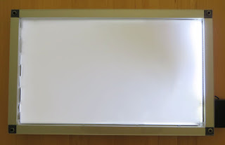
Using only the backlight diffuser which appears to be a type of translucent plastic film produces good uniformity. There were other optical sheets layered on the front of the original LCD although these were not used.


Light Table Test
Light Table Test
During cleaning of the acrylic with a dry cloth, the backlight diffuser became attracted to the acrylic and lifted off the backlight. An application of silicon helped reduce the lift of the backlight.