Friday, 27 December 2019

Salvaging Electronic Parts - Part 4 Breville BFP650

Summary
This blog is the next in the series focusing on salvaging electronic parts. For this post, a Breville food processor was broken down with a view to salvage the AC motor.


Breville BFP650
Breville BFP650
Image courtesy www.productreview.com.au 


Salvaging
There were several plastic screws and individual plastic pieces which required removal from inside the food processor which allowed the microswitches, circuit board and motor to be removed.

Microswitches
Four micro-switches from Merchant Corporation were removed from the food processor. Three of the switches were interfaced to the push buttons seen of the outside of the Breville unit and the last switch was associated with the bowl interlock switch.


Breville BFP650 Microswitches
Breville BFP650 Micro-switches
Shown in the image above are the Merchant Corporation switches SM-51 and SM-31F from the Breville. The SM-31F switch features a short throw mechanical operation with a domed actuator top.

Circuit Board
The circuit board for interfacing the switches and controlling the motor is a single sided board. The switching relay manufacturer is from Tianbo Relay. There are associated passives for speed control and driving the power LED.


Breville BFP650 Control Circuit Board
The relay is sealed at the base with a bead of clear silicone; this part could be salvaged. The two power resistors and diode may be handy for spares however parts such as the M205 fuse may not be worth salvaging.

On the solder solder side of the circuit board there is a straight forward routing layout. A noteworthy item is the use of slots in the board to address cable management. Items to avoid are the undersized pads for cables and the excess use of solder on many of the joints.


Breville BFP650 Control Circuit Board Solder Side
AC Motor
The weight of the Breville unit appears mostly due to the copper windings of the 1000W motor. Manufactured by Chasekin Limited (HK), part number YXQ-250A33, there is no website for the company so details regarding the motor are scarce. Curiously, Breville list a 5 year warranty for the motor and all the other items have a 2 year warranty.


Breville BFP650 Motor
To take a closer look at the motor internals the plastic cover, water catcher and mounting plate required removal.

Breville BFP650 Motor Top View
With the mounting plate removed, the nuts holding the motor frame were visible.

Breville BFP650 Motor Mounting Plate Removed
The motor was further disassembled by removing the cover (end bell).

Breville BFP650 Motor Assembly
Visible in the image above is the rotor to the left, stator towards the bottom and end bell towards the top. Not pictured, but mounted on the side of the motor windings, was a thermal fuse.

The rotor was packed at the ends with a set of steel and fiber washers however no bearings were visible in the end bell. The fixture was removed and located inside was a steel bush. No bearings meant that this motor could not be used for extended periods of time.

Breville BFP650 Motor Bush
Salvaging parts from the Breville BFP650 was a misadventure and could be considered misspent time; for this particular product the author concurs.

Breville BFP650 Hardware
Some parts were salvaged from the Breville and the motor could be taken for metal recycling. The design and quality of the parts however, mostly prevent reuse for other purposes.

Tuesday, 24 December 2019

Model Rocket Launcher Bluetooth Android

Summary
This post follows the development of Bluetooth model rocket launcher hardware (open source) with an Android phone application. For those interested in already completed designs, there exists projects for wireless model rocket launchers on Instructables, Model Rocket Forum, MakeZine or crowd funded sites such as Indiegogo. To paraphrase David Papp from his 2014 Indiegogo campaign, there is undoubtedly a requirement for model rocketry control and launching to be technologically brought out of the dark ages.

To expedite development of the prototype, the launcher project was based on an existing Cypress Bluetooth Robot design. The hardware component of the design was based on a Cypress BLE module and the Android application was derived from the Robot application. As pictured below, minimal changes were made to the Android Studio app. All credit to Cypress for the original design.


Example of Rocket Launcher Application
Wireless Design Features
The list below details several designs features of the prototype build.
  1. Fully isolated igniter. No power rails are connected to the igniter with a view to minimising incorrect ignitions
  2. Reverse bias battery protection. Diode protection to prevent false ignitions from incorrectly connected batteries with single FET designs
  3. Electronic switching with Smart Switches for igniter control
  4. Electronic switches with inbuilt overcurrent protection, voltage and current monitoring
  5. Optional monitor to check and or log launch current
  6. Optional OLED display for user feedback providing better full sun contrast
  7. Option to use a UHF module instead of Bluetooth
  8. Option to use a pushbutton for launching and no wireless communications
Schematic
Whilst looking for a Bluetooth module the range of parts was vast. From Microchip to Expresssif with digital to serial interfaces most were fit for purpose. Only after stumbling across the Cypress Robot with BLE App by Alan Hawse, which details most of the steps in building an application with Android Studio, was the Cypress BLE part chosen.

Bluetooth Module
The Cypress BLE module (CY8CKIT-143A) was selected for the launcher. For the PCB design software the schematic and PCB parts were drawn. Below are the schematic connections to the BLE Module. As usual the connections were allocated in conjunction with Cypress' PSoC Creator.


CY8CKIT-143 Rocket Launcher Schematic Connections
To design the PCB footprint for the module, Gerber files were imported into Altium using the technique described in a previous blog. From the Cypress PSoC 4 BLE Module Gerber pack, the PSM.art file was imported as it contained the module circuit board shape and the location of the pads for the two dual row headers. The file was renamed to PSM.cam, an opened in Altium resulting in the capture shown below.


Altium Imported CY8CKIT-143A DXF
No 3D model existed for the CY8CKIT-143A module so to indicate module positioning and sizing, two dual row male headers were placed as shown below.


CY8CKIT-143A PCB Library Part
For interface connections to the CY8CKIT-143A module, several inputs and outputs were added as options.


CY8CKIT-143 Rocket Launcher IO Connections
Decoupling and power supply filtering was implemented with the common ferrite - capacitor design seen on many PSoC development boards. The development module does contain some on-board filtering with ferrites connected to only a single connector (J3) and not the two main connectors (J1, J2).
CY8CKIT-143 Rocket Launcher External Power Supply Rails
Bluetooth Module Power Supply
The Bluetooth module has an operating voltage from 1.9V to 5.0V although for the prototype system the voltage was set to 5.0V. For those interested in power savings, the system voltage could theoretically be reduced to 2.5V; the caveat being the control voltage for the high-side driver which is listed as 2.1V.


CY8CKIT-143 Rocket Launcher 5V Power Supply
Shown above is the switch mode power supply which features the reverse bias protection for the power supply and the igniter high-side drivers.

Igniter Activation
Igniter activation is achieved using a pair of high and low side switches. The design of the circuit would facilitate removal of one of the switches although having a pair was considered the safest solution. Certainly a similar solution could be achieved with a half-bridge or similar device.


Rocket Launcher Igniter Activation Circuit
In terms of resistance in the active devices, the high side switch (VN7040AS) has a typical ON resistance of 40mR and the low side switch (VNL5030S5) typically 30mR. The total resistance of the switches is orders of magnitude lower than the resistance quoted for an Estes Igniter #302301 at 800mR. This should result in the suggested minimum current being met.

Igniter Current Sensing
Current sensing can be achieved using the high side switch, if the measurement is intended for high currents. It should be noted that the current sense ratio drift for the VN7040AS is + 5% for currents at 4.5A or + 30% for currents between 0.01A and 0.03A.


Rocket Launcher Igniter Current Sensing Circuit
An optional dedicated current sensing chip (INA219) was included in the design for higher accuracy current measurements. Even though this device is an older part, circa 2008, the device is well supported, senses the bus voltage from 0-26V, uses an I2C interface and has an accuracy of 0.5% over the operating temperature.

Display (OLED)
An OLED was chosen over an LCD because of the high contrast required in sunlight readable applications. Other factors which were considered include the operating temperature which for an OLED appears a standard -40 to +80C and that no external contrast setting is required for an OLED.


Rocket Launcher OLED (Optional) Circuit
Buzzer and LEDs
To provide audible feedback before activation of the igniter, a buzzer was included. Also shown in the image below were two LEDs, one for the Bluetooth status and the other for general operational status.


Rocket Launcher Buzzer and LED
RF Module
On a prior rocket launcher design, a straightforward 433MHz UHF remote transmitter and receiver module was used for controlling the rocket launch. The same UHF module was retained as an option in the Bluetooth design.


Rocket Launcher RF Module (Optional)
Manual Launch
For those requiring no remote control but the safety of high and low side switches, a manual push button launch switch was added to the design.


Rocket Launcher Manual Launch Push Button (Optional)
Managing Options
A number of options were included in the hardware and to manage these four version resistors were made available to the CY8CKIT-143A module.
Rocket Launcher Option Management
Firmware
For the PSoC microcontroller, the hardware and firmware were developed in unison. This process ensured systems such as the ADC were mapped to the most appropriate pins of the microcontroller.
PSoC Launcher Misc Components
The capture above shows the Bluetooth, I2C (ADC), UART (debug) and OLED components.


PSoC Launcher Timer Components
Below is the ADC component connected to the high side switch. The current sense output of the high side switch is passed through a resistor to provide a scaled voltage representative of the measured current.    


PSoC Launcher ADC Component
Three timers were allocated in the Launcher firmware. The first timer was a system tick timer, second a PWM for the buzzer and lastly a PWM to flash the Bluetooth LED.
PSoC Launcher Inputs and Outputs
In the above capture the remaining inputs and outputs were allocated. These consisted of control and feedback from the high, low side switches, hardware option inputs, UHF module inputs, UART hardware debug output and status LED.

Tick Timer Configuration
A tick 'system' timer was included in the design with a view to controlling the launching process.


PSoC Launcher Tick Timer
Buzzer Timer Configuration
To modulate the buzzer, a 3.9khz PWM was established.


PSoC Buzzer Timer
PSoC Buzzer Timer
LED Timer Configuration
To indicate the status of the launcher Bluetooth connection, an LED was driven by a timer using a slow PWM.


PSoC LED Timer
PSoC LED Timer

UART Configuration
For debug a UART was configured at 921600, 8, N, 1.


PSoC UART (Debug)
PSoC UART (Debug)
ADC Configuration
The ADC was configured for an unsigned result and an 8 bit resolution. This resulted in a quick sample rate and a step size of around 50mV.


ADC Configuration
ADC Configuration
Bluetooth Configuration
The setup of the Bluetooth in the Launcher PSoC application closely followed the Cypress Robot project which was covered in the post "How to Create a PSoC BLE App: Lesson 3 Configure the BLE Component". The capture below shows that a custom GATT server was configured.


Launcher BLE General
There were changes made to the Robot profile to suit the launcher. This profile and some of the services were renamed to suit. This service was configured with a field size of uint8.


Launcher BLE Launch Service
BLE Launch Service
As shown below a battery service was also added to the BLE for monitoring purposes. This service was configured with a field size of uint16.


BLE Battery Voltage Service
All remaining configuration was unchanged from the original Robot PSoC application.

Software
For testing and to limit the number of changes in Android Studio, the primary user interface (activity page) was updated. Corresponding changes were made in the associated Java files, MainActivity and PSoCCapSenseLedService. Shown below are the changes between the original Cypress BLE101 application and the updated application activity page.
Original Cypress BLE101 Activity Page
Updated Cypress BLE101 Activity Page
Unused features such as the CapSense and LED were removed from the Android Studio application. Provision for the battery voltage was added onto the activity page.

To confirm that the Android Studio application was able to connect with the Cypress BLE module, a straightforward test was made. A compatible phone was loaded with the updated Android Studio application and the BLE module, powered by the MiniProg programme, was loaded with the Cypress BLE application.
Cypress BLE Module MiniProg Powered
A Bluetooth connection was made between the phone and BLE module.

PCB Layout
Before starting the PCB layout, an enclosure was required to house the control printed circuit board (PCB) and battery. An ABS case with a clear cover was available from a local supplier, Jaycar, which comfortably fit the battery.


HB6412 Enclosure
HB6412 Enclosure - Courtesy Jaycar
With the battery moved toward one end of the enclosure this allowed plenty of room for the Bluetooth Control PCB. The dimensions of the PCB are shown below.
Bluetooth Control PCB Dimensions
Shown in the capture below is the PCB will all components placed onto the workspace. Parts such as the optional display and mounting holes already placed.


Bluetooth Control PCB Parts Placement
The PCB was designed for 4 layers which consisted of two external signal layers and two internal power planes. Shown in the capture below is the routing for the prototype board.


Bluetooth Control PCB Routed
Shown below are top and bottom layer captures of the control PCB loaded with all options.
Bluetooth Control PCB Top 3D
Bluetooth Control PCB Bottom 3D
Power Up Testing
Manufacture of the PCB was performed by Chinese company PCBWay.


Bluetooth Control PCB Top Layer

Bluetooth Control PCB Bottom Layer
For initial testing, the components associated with the 5V power supply and dual outputs were populated. A controlled power-up test was performed on a current limited supply. During this time the 5V switch mode supply was monitored for stability.


Control PCB Populated Power Supply and Drivers
With the on-board power supply operating as expected, the high and low side drivers were tested. The two headers required for the Cypress Bluetooth module were fitted which allowed the control lines for the drivers to be connected to the 5V supply.


Control PCB Populated BLE Headers
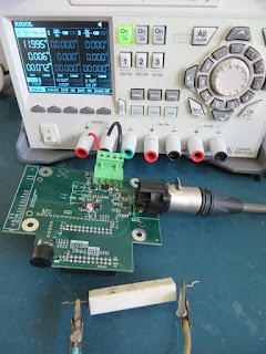
The hardware setup used for initial measurements of the high and low drivers under load is shown below.


Control PCB Driver Load Testing Setup
The following table lists two load measurements performed on the drivers.


Load Measurements
Load Measurements
Code Testing
As this project was inspired by the Cypress BLE Robot design, the original PSoC application was used as a template. Minor modifications were made to the BLE Callback and a state machine for the launch control. To test the code changes the BLE Module was plugged into the control PCB then the Bluetooth and Status LEDs fitted. These LEDs are indicated by the yellow box in the image below.


Control PCB with Cypress BLE Module Fitted
The red box in the image above indicates the on-board MiniProg programming connection. Linked below is the PSoC Creator 4.2 project used for testing.


OLED Testing
A community submitted PSoC Creator component was used for the OLED. All credit to Thanasis Georgiou for the component.
WS0010 PSoC Creator Component

A Winstar WEH1602 OLED was used for the project.


Winstar WEH1602 OLED
The relevant header was soldered onto the PCB then the OLED fitted.

Powered OLED on Control PCB
To secure the OLED to the main control PCB, four M2.5 x 12mm metal standoffs were used.


OLED 12mm Standoffs
OLED 12mm Standoffs
For the messages shown on the OLED, only a few modes were used which included a countdown timer. Brief video of the operation is shown below.


Enclosure
The plastic enclosure was supplied with an internal metal mounting plate which was used as the base the control PCB. Metal standoffs, M3 x 25mm, were required to space the control PCB from the metal mounting plate due to the height of the DIN connector.


Control PCB Mounting Plate
To facilitate access to the DIN connector, one of the metal latches was removed from the enclosure. 


DIN Launch Connector
The control PCB was justified to the right side of the enclosure to ensure that the DIN connector eject button was accessible.


Control PCB Mounted
Control PCB Mounted
To secure the battery in place, a steel plate was fashioned then covered in heatshrink. One of the mounting holes for the metal plate was repurposed for securing the battery. A second hole was added to the metal plate with an M4 nut soldered to the rear of  the plate. 


Assembled Launcher
Assembled Launcher
A key-switch was added to the case then the battery wires were added. The image above shows the mock-up of the launcher.

Launch Cable
To connect between the launch controller and the igniter, an IEC mains cable was repurposed. An XLR connector was fitted for the launcher interface and crocodile clips were soldered on the opposite end.


XLR Launch Cable
XLR Launch Cable
Field Testing
Field testing was performed with a range of Estes igniters. The clips below show some of the launches performed.


Project Files
Listed below are the schematics, Gerber files, PSoC Creator 4.3 project archive and the Android application. Android source can be supplied.


Launcher Schematics
Launcher Gerber Files
PSoC Creator 4.3 Archive
Android Application 

Final Thoughts
There are a number of updates and additional features to add to the project. Some of these features include monitoring the battery voltage and current during a launch. These will be investigated in a subsequent blog!