Showing posts with label salvaging. Show all posts

Sunday, 30 March 2025

Salvaging Components from DPF-HD1000

Introduction 
This post looks at electronic components that could be salvaged from a Sony digital photo frame, DPF-HD1000 (circa 2010).

Tear Down
Four plastic screws secure the two halves of the photo frame case. A thin prying tool was used to release the internal plastic clips.

DPF-HD1000 Front Cover Removed

Removing the front panel shows the LCD and two peripheral items, an IR sensor and an LED strip.

Internals of the Photo Frame
Shifting the position of the display shows the main Printed Circuit Assembly (PCA) and the board to peripheral connections.

DPF-HD1000 with PCA Exposed

The IR receiver was connected with a 3-pin cable to the main PCA. The markings on the sensor appear to be 28m5 and E23, but there is no data available for the part online. The connections to the sensor could possibly be determined from the cable colours.

DPF-HD1000 LED Logo Board

The small LED PCA was labelled ‘logo LED board’ circa 2011. This board was used to illuminate the Sony logo built into the front plastic cover.

DPF-HD1000 LED Logo Board Powered

From the website Panel Look, the LCD appears to be from CPT, although discontinued, and could be used for repair or paired with a converter board capable of driving 60-pin flat flex cables from various interfaces such as USB.

DPF-HD1000 LCD Part Number

After removing the 4 screws retaining the PCA, the entire electronic assembly could be removed.

DPF-HD1000 Complete Electronics Assembly

Disconnecting all the peripherals from the PCA, attention turned to some interesting components on the main PCA. The PCA was labelled ‘Sony Basic 10DW MP’.

Possible PCA Component Salvaging
The USB connectors, surface mount and vertical switches could be salvaged from the PCA. The combination card holder on the PCA was an interesting component (large component on the right of the PCA); no data could be found from the A238B marking on the device.

DPF-HD1000 PCA Side 1

Upon reviewing the passives, inductors and the common mode filter near the DC jack (bottom right) these could be salvaged and reused. Due to the age of the PCA, the SMT electrolytic capacitors are not recommended for salvaging, although they did appear in near-new condition.

For active devices, the single linear regulator 1117T near the SD card holder could be salvaged.
DPF-HD1000 PCA Side 2

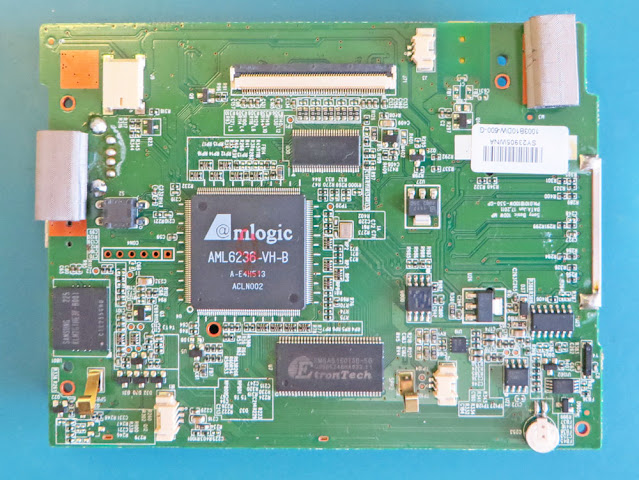
Flipping the PCA shows several chips, connectors for the peripheral devices and a smattering of passives. If any external devices, such as the IR sensor, were earmarked for salvage, the surface mount connectors could also be salvaged from the PCA.

To the left of the main Amlogic controller is a surface mount switch which may be responsible for detecting rotation (movement) of the display. When shaking the PCA, the internal mechanism can be heard moving. The component marking is EnSky, however no data could be located on the switch.

There is an oscillator, possibly 24 MHz (middle PCA), driving the Amlogic controller and a watch crystal for the on-board RTC (PCA bottom right) that may be useable.

An ELNA button supercapacitor, rated at 3.3 V 0.22 uF, provided backup for the RTC. Looking at the supercapacitor, corrosion was sighted on the case of the device and therefore not useable.

Corrosion on Supercapacitor

The main controller AML6236-VB-B is not listed on the Amlogic website and is likely not worth salvaging.

For storage, Sony opted for a Samsung 2 GB eMMC, part number KLM2G1HE3F-B001 (far left on PCA2). While this component does not appear to be manufactured any more, it would be a great device for experiments. The PCB model still appears to be available (SnapEDA). Even though the component may need to be reballed when fitting the component to a new PCA, connection to micros such as ST or Microchip would most likely be possible.

The 512 Mbit DDR1 memory was provided by Etrontech, part EM6AB160TSD-5G. This part could be used for repairs.

Interfacing the Amlogic controller to the LCD was a Texas Instruments flat panel driver part number SN75LVDS83B. The datasheet is an interesting read and even contains a good summary of PCB layout techniques.

Some other active components on the PCA are the serial flash, switching and linear regulators, speaker driver and RTC. There is also an unmarked chip on the board whose purpose is not clear. Many of these components could be salvaged depending on requirements.

Component Salvaging Example
Often questions posted after salvaging blogs relate to how components are removed from PCAs. As an example, consider the removal of the DC jack from the PCA.

Setup for Component Removal

The jack component is a 5-pin device that could be desoldered although in this example it was removed using a heater plate. Firstly, all the components on the opposite side of the DC jack were removed. These components consisted primarily of passives. This side of the board was made as flat and clean as possible. Then a heater plate, in this instance a MiniWare MHP50, was used to preheat the side of the PCA where the passives were removed (beneath the DC jack). Shortly after the heating cycle, a reflow cycle was run to pry the jack from the PCA. This technique certainly cannot be used for every board and component as the component population density and board construction can have significant effects on heating.

Salvaged DC Power Jack

Other tools such as a hot air desoldering tool or a small temperature controlled oven may be better suited for the removal of specific components.

Tuesday, 5 December 2023

Salvaging from a WAG120N Router

Introduction
This blog looks at salvaging parts and designs from a Linksys ADSL router model WAG120N.

WAG120N
WAG120N (Courtesy Google Images)

Parts Salvaging
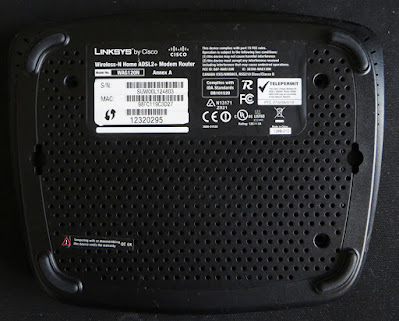
Firstly flipping the router over to reveal the base of the unit, there are four plastic screws retaining the lid. After removing the screws, the lid can be detached from the base (two plastic shells) with a small flat-blade screwdriver or plastic prying tool.

Bottom View of WAG120N Router

Removing the lid shows the internals of the router; a circuit board and a dedicated antenna.

Internal View of WAG120N Router

Circuit Board - Top Side
The DC-DC Stepdown converter from ITE Tech part CAT7105CA (purple box in image below) is not listed as a part online; the status of the part is unknown. Not worth salvaging unless for a repair to a similar router.

Identified Parts of WAG120N Router Circuit Board - Top Side

The serial flash from Taiwanese manufacturer
Macronix International, part MX25L3206EMZI-12G (red box), is not large in capacity but could be salvaged. As with other parts, this part appears to be obsolete.

Capacitor manufacturers are Leylon and Luxon. These parts appear to be in good condition although for the age of the router, these may not be worth salvaging.

There are two through-hole crystals on the board, 25 MHz and 36 MHz (black box). Depending on needs, either crystal could be useful for small or hobby projects.

Under the small aluminium heatsink is the part responsible for the 802.11 communications, Ralink RT3050F (yellow box).

Other parts such as the memory (green box), ADSL controller (blue box) and the enclosed metal can device were not reviewed. The remaining items such as the LEDs could be easily salvaged.

Salvaging the mechanical items such as the switch, power jack, push button and connectors could be possible with the appropriate equipment.

Circuit Board - Bottom Side
The linear regulator used on the board appear to be manufactured by General Semiconductor which was acquired by Vishay Semiconductor some years ago. The part on the circuit board GS117A (red box in image below) appears to be obsolete although this is a jelly bean regulator.

Identified Parts of WAG120N Router Circuit Board - Bottom Side

Some parts with markings, NF B1386L, are possibly a Unisonic transistor 2SB1386L (blue box), not worth salvaging.

External and Circuit Board WiFi Antennas
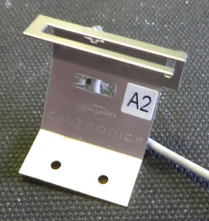
The external antenna pictured below from Galtronics could not be located as a product on the Galtronics website. The antenna may have been a custom design for the Linksys router.

Galtronics Router Antenna
Galtronics External Router Antenna

The mechanical antenna may be an interesting part to experiment with. For the second WiFi antenna, this is designed into the circuit board as pictured below.

Circuit Board Antenna for Router

Both antennas could serve as reference design in the WiFi domain by providing dimensions or a circuit board layout.

Summary
In general, the physical parts from the Linksys router were not worth salvaging. However, the dedicated external WiFi antenna from Galtronics was an interesting hardware design.


Monday, 27 December 2021

Salvaging Motorola MBP11

Summary
This blog performs a teardown of the Motorola MBP11 baby monitor, comprised of a transmitter and receiver unit, for the purpose of salvaging electronics.

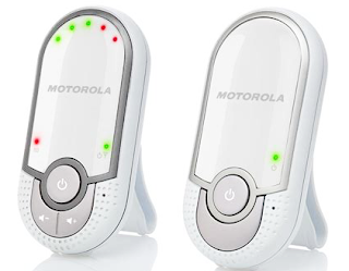
Original Image Motorola MBP11
Original Image Motorola MBP11 (Rights reserved)

Dismantling
The receiver unit of the MBP11 was commonly battery powered by a small NiMH battery. Removing the battery cover allowed access to two plastic screws holding the two-part case together. Whilst the battery could be salvaged, the battery chemistry and capacity may limit use.
For the MBP11 transmitter unit, the two plastic screws holding the case together were accessible from the rear of the unit.
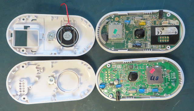
Removing one side of the plastic housing provided access to the circuit boards as shown below.

Opened Cases of Motorola MBP11 Units

Receiver Unit
Holding the receiver circuit board in position were additional plastic screws. The speaker connections were disconnected when the half plastic cases were brought apart.

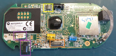
Located on the circuit board were only a handful of salvageable items. The processor was the usual ‘blob’ solution and the RF was all handled in a metal can fitted to a castellated daughter board.

The orange box in the image below shows the 13.842 MHz surface mount crystal used by the unit.

Identified in the yellow box, a serial memory device. The FRAM serial memory part FM24C16B would be worth salvaging especially due to the long data retention of FRAM.

Motorola MBP11 Receiver Circuit Board

Connectors shown by the purple box may come in handy if the battery or external DC 6 V plug pack were used for another purpose.

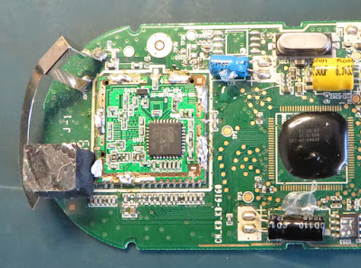
Out of curiosity the metal can on the castellated RF board was removed.

Under the RF Can on the MBP11 Receiver Circuit Board

Under the metal can was an RF chip, DE 19RF 19CNC, from a chip manufacturer called DSP Group. No immediate datasheet could be located for the chip.

Although the RF chip may not be worth salvaging, the implementation behind the castellated daughterboard is a good example of what can be achieved especially with RF.

There are a few takeaways for new circuit board designers attempting castellated boards including items such as the castellated pad spacing, RF shielding and component placement. As an example, shown by the red box in the image below, the power rail (one side) was decoupled on the main circuit board immediately after the via, then at the RF chip itself.

Decoupled Power Highlighted for Receiver Castellated Circuit Board

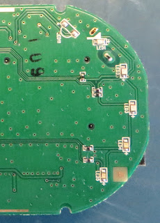
There were seven LED's on the rear of the circuit board that could also be salvaged. Five LED's provided visual feedback for the sound level detected and the remaining indicating connectivity and power. Worth salvaging just for prototype boards.

LED's on MBP11 Receiver Circuit Board

Transmitter Unit
Similar to the receiver unit, the transmitter circuit board was held in position were two additional plastic screws.

The same ‘blob’ solution and RF in a metal can was present on the transmitter board with no castellated circuit board.

The orange box showed the same 13.842 MHz surface mount crystal as the receiver and the yellow box shows the same FRAM device.

Identified by the purple box was the power connector jack.

Motorola MBP11 Transmitter Circuit Board

Highlighted by the black box, the solitary surface mount capacitor. Manufacturer unknown.

Additionally, a linear regulator was present on the transmitter. The red box shows the LM1117. This device could be salvaged also.

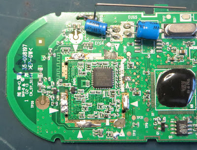
The metal can was removed to show the same RF chip as the receiver unit, DE 19RF 19CNC.

Under the RF Can on the MBP11 Transmitter Circuit Board

For both boards, the leaded electrolytic capacitors showed no signs of wear and could be salvaged if needed. All manufacturers of these electrolytic capacitors are not well known. However, some devices are rated to 105°C. Similarly, there are dozens of passive components on the board that could be pried off if required.

Additional Salvaged Items
 

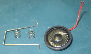
There were additional items such as the PCB mount microphone, external speaker, metal clip and springs that could come in useful for a variety of jobs.

Final Thoughts
There were further items to keep in mind regarding the technology used by these circuit boards such as the gratuitous use of test points, the practical use of via stitching in the RF area and associated power traces.

One item of caution however was the lack of Lead-Free marking on the circuit boards. For the intended target market of the Motorola MBP11, Lead-free would be no less than expected. However, as Lead-free was not noted on the circuit boards, for those salvaging from this or any such device, the appropriate preventatives should be taken.

Friday, 27 December 2019

Salvaging Electronic Parts - Part 4 Breville BFP650

Summary
This blog is the next in the series focusing on salvaging electronic parts. For this post, a Breville food processor was broken down with a view to salvage the AC motor.


Breville BFP650
Breville BFP650
Image courtesy www.productreview.com.au 


Salvaging
There were several plastic screws and individual plastic pieces which required removal from inside the food processor which allowed the microswitches, circuit board and motor to be removed.

Microswitches
Four micro-switches from Merchant Corporation were removed from the food processor. Three of the switches were interfaced to the push buttons seen of the outside of the Breville unit and the last switch was associated with the bowl interlock switch.


Breville BFP650 Microswitches
Breville BFP650 Micro-switches
Shown in the image above are the Merchant Corporation switches SM-51 and SM-31F from the Breville. The SM-31F switch features a short throw mechanical operation with a domed actuator top.

Circuit Board
The circuit board for interfacing the switches and controlling the motor is a single sided board. The switching relay manufacturer is from Tianbo Relay. There are associated passives for speed control and driving the power LED.


Breville BFP650 Control Circuit Board
The relay is sealed at the base with a bead of clear silicone; this part could be salvaged. The two power resistors and diode may be handy for spares however parts such as the M205 fuse may not be worth salvaging.

On the solder solder side of the circuit board there is a straight forward routing layout. A noteworthy item is the use of slots in the board to address cable management. Items to avoid are the undersized pads for cables and the excess use of solder on many of the joints.


Breville BFP650 Control Circuit Board Solder Side
AC Motor
The weight of the Breville unit appears mostly due to the copper windings of the 1000W motor. Manufactured by Chasekin Limited (HK), part number YXQ-250A33, there is no website for the company so details regarding the motor are scarce. Curiously, Breville list a 5 year warranty for the motor and all the other items have a 2 year warranty.


Breville BFP650 Motor
To take a closer look at the motor internals the plastic cover, water catcher and mounting plate required removal.

Breville BFP650 Motor Top View
With the mounting plate removed, the nuts holding the motor frame were visible.

Breville BFP650 Motor Mounting Plate Removed
The motor was further disassembled by removing the cover (end bell).

Breville BFP650 Motor Assembly
Visible in the image above is the rotor to the left, stator towards the bottom and end bell towards the top. Not pictured, but mounted on the side of the motor windings, was a thermal fuse.

The rotor was packed at the ends with a set of steel and fiber washers however no bearings were visible in the end bell. The fixture was removed and located inside was a steel bush. No bearings meant that this motor could not be used for extended periods of time.

Breville BFP650 Motor Bush
Salvaging parts from the Breville BFP650 was a misadventure and could be considered misspent time; for this particular product the author concurs.

Breville BFP650 Hardware
Some parts were salvaged from the Breville and the motor could be taken for metal recycling. The design and quality of the parts however, mostly prevent reuse for other purposes.