Showing posts with label controller. Show all posts

Monday, 30 March 2026

Drill Press Controller Update Part 5

Introduction 
This post details the validation of the remaining hardware item on the drill press controller and Printed Circuit Board (PCB) updates.

Debug Validation
A series resistor was fitted between the microcontroller (PSoC) and the debug (TTL RX, TX) connector to serve as a basic type of input protection. During testing, the serial communications (USB to TTL converter) were intermittent, so the series 100 R resistor was reduced to 10 R to ensure reliable operation.

Updated Serial Input Resistors

PCB Update
As noted in the previous blog, the footprint of the input device (MAX22191) on the PCB required updating.

Updated Footprints on ESTOP PCB

During the PCB update, the top-layer silk screen text near the input and output connectors was increased to 1.5 mm.

Updated Text at Inputs on PCB
 
Updated Text at Outputs on PCB

To allow for easier hand soldering, a selection of component pads was increased.

ESTOP Mains Input Capacitor Pad Sizes

Updates were made to the power supply (AC-DC) and mains input capacitors.

ESTOP Mains Input Capacitor Pad Sizes Updated

The image below shows the updated board.

ESTOP PCB Update

ESTOP PCB Update

Next, building the updated PCB, reviewing the mounting of the solid-state relay in the original enclosure shown below, and testing with the existing drill press setup.

Existing ESTOP Electrical on Drill Press

Tuesday, 16 December 2025

Drill Press Controller Update Part 4

Introduction 
This blog 
details the fitting of the drill press controller's input circuitry and simple validation testing of the updated input circuitry.

Input Device Validation
In the earlier drill press post describing updates to the controller, the input circuitry (24 V) was changed from using discrete components to the PLC (Programmable Logic Controller) input device, the MAX22191, from Analog Devices.

The PLC input devices were soldered to the prototype board along with the input connector. It should be noted that the footprint for the MAX22191 on the board was found to be incorrect; however, testing was still possible.

Controller and Sensor Test Setup

Controller and Sensor Test Setup 

The output of a power supply was connected to one of the PLC inputs, and the ON/OFF thresholds were measured by varying the voltage to the MAX22191 in 100 mV increments. The approximate threshold voltages were measured for an ON at 8.9 V, and the OFF voltage was 7.8 V. These voltages fall within the range specified by the ‘IN Voltage Upper Threshold’ and ‘IN Voltage Lower Threshold’ as stated in the MAX22191 datasheet.

Connecting a Proximity Sensor
The drill press controller utilises a proximity sensor to detect the spindle speed, with the output signal from the sensor resembling a square wave. The proximity sensor was connected to one of the MAX22191 inputs for testing. The output of the MAX22191 connects directly to the microcontroller (PSoC), so a pass-through connection was made in the PSoC for testing purposes. Using the PSoC fabric, the sensor input was routed to a test pin, which had a test pad.

PSoC Creator Spindle Pass-Through Connection

Shown below is a pulse from a magnetic sensor and the PSoC test pin, as measured by an oscilloscope. Oscilloscope channel 1 represents the input to the MAX22191, and channel 2 represents the PSoC test pin output. Upon reviewing the input and output signals, there is little difference in the timing of the signals, which is ideal for ensuring no change to the spindle 
speed measurement.

Sensor Test Pulse Measurement

As an additional check, the delay from the proximity sensor to the rising edge of the output signal was also captured, as shown in the image below.

Sensor Test Pulse Rising Edge Measurement

In the next post, the final check will be performed on the debug channel, which is a TTL signal, and the circuit board will be updated with any changes.

Sunday, 5 October 2025

Drill Press Controller Update Part 3

Introduction 
This blog details 
retesting the drill press controllers' DC-DC power supply, fitting components related to the outputs and testing the output drivers.

Retesting the Power Supply
The original inductor fitted to the PCB (Printed Circuit Board) was removed and replaced with a 10 μH inductor. Testing the supply with the same load as the last post, the regulation at 165 mA and 330 mA was better than 0.1 %. The unloaded voltage was measured at 3.36 V, which is within component tolerances.

A short regulation test was made on the output of the AC-DC bricks after fitting the necessary parts to the PCB. The bricks output was as expected in tolerance.

PCB Setup for Power Supply Testing


Fitting Output Connected Microcontroller
The microcontroller and associated output hardware were fitted to the PCB, after which tests were performed. For the relay outputs, the output driver VND5160J was fitted to the PCB and then load tested. Separate FDN337N devices control the emergency stop and status LEDs, which were also checked.

Solid State Relay (SSR) Outputs
Following the fitting of the microcontroller and the output driver for the SSR, an external AC supply, SSR, and mains lamp were connected.

Instead of the previously mentioned SSR from TE, part SSRD-240D25A, a Multicomp MPKSI240D10-L(070) was selected. The control voltage for the Multicomp part is between DC 4 – 32 V, meaning an installation can be configured with one or two SSR devices. The clip below shows a lamp connected through the SSR powered by a transformer. The PSoC was programmed to toggle the SSR control input.


For reference, the output of the SSR was captured on an oscilloscope.

SSR Output
SSR Output

Status and Emergency Stop LEDs
The EAO illuminated pushbutton featured in the original drill press design was listed as superseded and replaced with the EAO part 84-5241.2B20. The original code was updated to flash the status LED, indicating the code was operating. No changes were needed for the Emergency Stop LED. In the clip below, both LEDs are shown operating.


In the next post, the input circuitry will be fitted and tested.

Thursday, 31 July 2025

Drill Press Controller Update Part 2

Introduction 
This blog details the completion of the drill press controller's printed circuit board (PCB) layout, a partial build of the power supply and testing.

Model of ESTOP PCA Mated to the Enclosure

Placement of New Components
In the previous post, the PCB shape was defined to suit the enclosure. In this post, the component placement and board routing were performed. Even though the design has a relatively low component count, attention was still paid to the mains (AC-DC) power supply and the low-voltage signals. Isolation and component clearances were made a priority.

Unrouted ESTOP Controller PCB

In the above capture, the AC to DC power supply (PSU1) is located on the PCB's left side. The right side of the PCB contains low-voltage parts, such as the microcontroller, input and driver devices.

Unpopulated PCB Housing
After the component placement was finalised, a 3D model of the PCB was generated using the PCB design software. This approach was taken to check for mechanical interference between the PCB and the enclosure model. The check between models was achieved using Fusion 360.

PCB Mated with Enclosure Base

 The design uses the connectors provided with the enclosure.

PCB Mated with Enclosure Base and Cover

With no interference detected between objects, the PCB was routed.

Routed PCB and Layers
The PCB was designed using a standard 4-layer 1.6 mm PCB stackup provided by the manufacturing house.

PCB Top Layer
PCB Top Layer

PCB Mid Layer 1
PCB Mid Layer 1

PCB Mid Layer 2
PCB Mid Layer 2

The PCB bottom layer was a copper fill under the low-voltage section and not shown in this post.

Manufactured PCB and Population 
To populate a new PCB, I prioritise installing the power supply first. However, as the controller PCB is double the size of the reflow device (e-Design Miniware MHP50), more difficult parts were soldered first.

Reflow Part on a MiniWare

The driver chip with an exposed pad was reflowed first.

Power Supply Population
Next, out of the two onboard power supplies, the discrete switch-mode DC 5 V regulator was fitted to the board.

Power Supply Bench Test

Testing was performed by directly supplying power to the relevant connections on the board. The turn ON voltage was noted at 6.8 V with the unloaded accuracy better than 2 %. With a 165 mA resistive load, the voltage regulation was better than 0.6 %. However, with a 330 mA load, the voltage regulation fell to 3.6 % which was likely due to the inductor. A different inductor will be tested in the next post, together with the additional PCB components.

Saturday, 31 May 2025

Dill Press Controller Update

Introduction 
This blog details improvements to a drill press controller created in a previous blog.

Why an Update?
With features such as sensing a stalled chuck, the drill press controller project was something of an experiment for home. Enquiries to this day persist for a ‘user-friendly installable’ version of the drill press controller. As many users seem to prefer a ready-to-go solution, the circuit board change in this post is a step towards simplifying the original controller design, but with some experimental improvements.

What Consolidation and Improvements?
The external DIN rail DC supply from the previous design could be incorporated onto the updated controller board. To fit an AC to DC module to the controller board, however, the controller enclosure would need to be changed from the original type.

Additionally, the AC contactor, which disables the drill press motor when an ESTOP event occurs, was identified as a space-consuming item. A subsequent post will review SSR (Solid State Relay) testing and, if useable, replacing the contactor.

Changes to the Design
Integrating an AC to DC supply onto the circuit board raised some technical questions. Firstly, what voltage should the DC output be? The second question is whether the voltage is suitable for other components in the system. Included in the list of other components are the SSR inputs and existing hardware, such as the ESTOP pushbutton LED.
For testing, a high-current dual form A SSR TE part (SSRD-240D25) was chosen.

TE SSRD-240D25 Solid State Relay

New Enclosure
Using the circuit board dimensions from the original controller as a guide, an enclosure from the manufacturer, Phoenix Contact, part 1311009 (BC 107,6-KIT-U11-7035+4SPTA12), was chosen. This part was selected because it was a two-part case with circuit board mounting, supplied with terminal circuit board terminals, and was affordable.

Phoenix Contact Enclosure #1311009

Schematic Changes
An AC-DC brick from Vigortronix was selected with a DC 12 V output. The VTX-214 series is manufactured with several DC output voltage options.

Updated Power Supply Schematic

As an experiment, a single input PLC device from Maxim was chosen to replace the previous input circuit.

Updated Input Schematic

In the previous design, the contactor coil was powered by two driver chips. For the updated design, the output was changed to instead drive the two enable inputs of the SSR or a similar device.

Updated Output Driver Schematic

Circuit Board Size and Shape
The technical datasheet for the 
Phoenix Contact enclosure does not appear to provide a dimensioned circuit board example. However, there is sufficient information in the technical drawing to define the circuit board shape. In fact, the 3D model of the enclosure from the Phoenix Contact website also contains an excellent example of circuit board mounting options. In the image below, Fusion 360 was used to hide the outside case of the enclosure.

Example of Circuit Boards in Phoenix Contact STEP Model

To validate the circuit board shape in the circuit board design software, the Phoenix Contact STEP model was required without all the example board options. Fusion 360 was used to suppress all but the plastic base in the STEP file. This STEP file was imported into the circuit board software to validate the circuit board shape.


Example of STEP File Imported into Circuit Board Design Software

In the next blog for the updated controller, the PCB layout is completed.

Sunday, 5 April 2020

Rexon RDM150D Retrofit ESTOP Stage 2

Summary
This blog details the second stage retrofit of a Rexon RDM150D drill press. The second stage added movement monitoring of the spindle and a requirement to  deactivate the drill press run switch after triggering the ESTOP. The first stage retrofit blog contained details relating to controller design and the drill press wiring.

Electrical Wiring - Stage 1
The first stage changes to the drill press electrical, which included the ESTOP button and controller, are shown in the image below.


Rexon RDM150D Stage 1 Electrical

Electrical Wiring - Stage 2
For the second stage retrofit, a proximity switch and a relay were added to the design. Both the new devices were connected to the controller.


Rexon RDM150D Stage 2 Electrical
Inductive Sensor
For detection of rotational movement in the pulley responsible for driving the spindle, an inductive sensor was selected.
MCPIP-T12L-001 Courtesy Multicomp
      MCPIP-T12L-001 Courtesy Multicomp

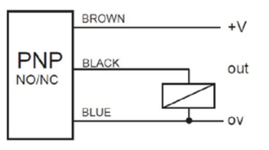
The sensor was manufactured by Multicomp, part MCPIP-T12L-001, which features a PNP output, M12 thread and a 2mm sensing distance.


Inductive Sensor PNP Electrical Connections
DIN Relay
A relay was added to detect when the manual switch (DPDT) was in the ON state. Providing the manual switch state to the controller served two purposes, firstly the controller could determine when the spindle was active and secondly the same feedback signal could be used to ensure that the manual switch was OFF before the contactor was reactivated.


DIN Relay 2909526 Courtesy Phoenix Contact

The relay used was a DIN style, 240V input, from Phoenix Contact.

As shown in the second stage electrical drawing above, the input to the relay was driven from the equipment side of the manual ON OFF switch. The pair of secondary side relay Normally Open connections were individually connected to 24V and the Spindle Active input of the controller.


Sensor Hardware and Mounting
An oversight with the Multicomp sensor installation was the devices body length which prevented the sensor being mounted between two pulleys.


Sensor Mounting Bracket
To mount the sensor inside the top housing of the drill press, a repurposed wall bracket was drilled to the required hole size (M12). Loctite 243 was used on the sensor thread. The bracket was fitted at an angle as shown in the above image. This prevented use of the lowest belt position between the spindle and middle pulleys. A shorter sensor, placed parallel to the belts, would be recommended for those implementing this design.

Triggering the sensor was achieved using a small steel angle fitted to the pulley. For a speed of 3000 RPM, best results were achieved when the length of the steel angle was 20 mm. Two M3 bolts with Loctite 243 and internal star washers were used to fix the steel bracket in position.


Sensor Steel Pulley Bracket

Sensor Test Measurement
With the Multicomp sensor powered and an Oscilloscope fitted to the Out connection, one measurement was taken at a slow RPM and the second measurement at the fastest RPM.

Slow RPM Sensor Measurement

Fast RPM Sensor Measurement

Relay Mounting
The DIN relay was mounted between the contactor and the controller, as pictured below.

Electrical Enclosure DIN Relay Mounting

PSoC Inputs
The spindle and spindle active inputs to the PSoC controller were provisioned in the first stage controller design. Connections were made according to the updated inputs detailed in the section below.

PSoC Inductive Spindle Input

Controller Wiring
A correction was required to the controller PCB overlay. The capture below shows the updated overlay reflecting the controller connections.

Retrofit Rexon Controller Updated PCB Overlay

Controller Option
To identify new features were added to the controller, one of the option resistors was populated on the controller PCB.


Enabling Controller Option on PCB

PSoC Code Changes
The principal change to the PSoC was the addition of logic for counting pulses from the inductive sensor.


PSoC Windowed Pulse Counter

A timer solution was implemented fifty percent duty cycle with a period of 499 ms. During the On time the Timer_Spindle component accumulated counts from the Spindle input. At the end of the capture the isr_Spindle fires allowing the count value to be retrieved. For the remainder of the period no counting was performed. The Sync component was used to synchronise the slower PWM_Spindle clock with the Timer_Spindle clock.

Monitoring of the spindle active input and spindle speed was moved into a basic state machine, extract listed below.


/**
* @brief Basic State Machine for handling ESTOP and Spindle signals
*/

void State_Mach_Mon(void) 
{
    switch (Spindle_Monitor_State)
    {
    case (state_m_idle):
        if (Status_ESTOP_Read() == 1u)
        {
            Spindle_Monitor_State = state_m_es_deact;
        }
    break;

   case (state_m_es_deact):
        Control_ESTOP_Write(0x1); 
        if (Status_ESTOP_Read() == 0u)
        {
            Spindle_Monitor_State = state_m_reset;
        }

        if (Spindle_Active_Read() == true)
        {
            PWM_Spindle_Start();
            Timer_Spindle_Start();
            Spindle_Monitor_State = state_m_es_sp_act;
            Spindle_Started = true;
            Spindle_Timer = 100u; 
        }
    break;

    case (state_m_es_sp_act):
        Spindle_Count_Update();
        if (Status_ESTOP_Read() == 0u)
        {
            Spindle_Monitor_State = state_m_es_reset;
        }

        if (Spindle_Active_Read() == false)
        {
            Spindle_Monitor_State = state_m_reset;
        }

        if ((Spindle_Counts == 0) && (Spindle_Timer == 0))
        {
           Spindle_Monitor_State = state_m_es_reset;
        }
    break;

    case (state_m_es_reset):
        PWM_Spindle_Stop();
        Timer_Spindle_Stop();
        Control_ESTOP_Write(0x0); 
        Spindle_Started = false;
        if (Spindle_Active_Read() == false)
        {
            Spindle_Monitor_State = state_m_idle;
        }
    break;       

    case (state_m_reset):
        Control_ESTOP_Write(0x0);
        PWM_Spindle_Stop();
        Timer_Spindle_Stop();
        Spindle_Monitor_State = state_m_idle; 
    break;
    } 
}


Additional changes were made in the code to read pulses measured by the spindle sensor counter and also to determine the configuration of the PCB version (function) resistors.

Option Resistors
Notes for the code option resistors was into the PSoC project.


PSoC Notes for Option Resistors

In the PSoC code, the various resistor combinations were used to define the controller operation.

/**
* @brief Board Options
*/
void Board_Options(void)
{
    if ((Option0_Read() == false) && (Option1_Read() == false))
    {
        System_Flags.Option_None = true;
        UART_UartPutString("No option\r\n");
    }
    else if ((Option0_Read() == true) && (Option1_Read() == false))
    {
        System_Flags.Option_Spd_Mon = true;
        UART_UartPutString("Speed monitor option\r\n"); 
    }
    else if (((Option0_Read() == true) && (Option1_Read() == true)) || ((Option0_Read() == false) && (Option1_Read() == true)))
    {
        UART_UartPutString("Unknown option\r\n"); 
    }
}


Sensor Counts
As the pulse counter configuration provided a 250 ms sampling window, the multiplier for the number of counts was set to 240.

/**
* @brief Read Spindle Counts and Report
*/
void Spindle_Count_Update(void) 
{
    if ((Spindle_Data_Ready == true) && (Spindle_Started == true))
    { 
        Spindle_Counts = Spindle_Raw*240u;
        Spindle_Data_Ready = false;
        ReportData();
    }
    Flag_Timer = false;
}

The Report Data function was used to provide the spindle speed in RPM. Data was output on a UART as shown in the capture below from TeraTerm.


Controller Spindle Speed Output in TeraTerm

A timer, defined by variable Spindle_Timer, ensured that when the spindle was not spinning for one second, the drill press motor would be switched off using the contactor.

Final Thoughts
The controller in this blog could be adapted for other workshop machinery, which was not originally manufactured with a method to stop that machinery in a controlled manner. Features such as the spindle rotation monitoring could be removed or disabled and other features added to suit the machine setup.

Downloads


ESTOP v1.1 BOM XLS
ESTOP v1.1 BOM XLS
ESTOP v1.1 Schematics PDF
ESTOP v1.1 PCB PDF
ESTOP v1.1 PCB PDF
ESTOP v1.1 Gerbers
ESTOP v1.1 Gerbers
ESTOP  v1.1 PSoC Doxygen
ESTOP v1.1 PSoC 4.3 Project
ESTOP Module PSoC Creator Top Design PDF