Summary
This blog performs a teardown of the Motorola MBP11 baby monitor, comprised of a transmitter and receiver unit, for the purpose of salvaging electronics.
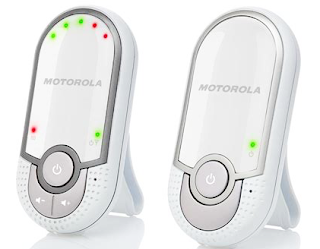 |
| Original Image Motorola MBP11 (Rights reserved) |
Dismantling
The receiver unit of the MBP11 was commonly battery powered by a small NiMH battery. Removing the battery cover allowed access to two plastic screws holding the two-part case together. Whilst the battery could be salvaged, the battery chemistry and capacity may limit use.
For the MBP11 transmitter unit, the two plastic screws holding the case together were accessible from the rear of the unit.
Removing one side of the plastic housing provided access to the circuit boards as shown below.
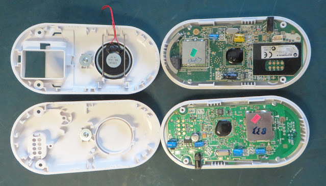 |
| Opened Cases of Motorola MBP11 Units |
Receiver Unit
Holding the receiver circuit board in position were additional plastic screws. The speaker connections were disconnected when the half plastic cases were brought apart.
Located on the circuit board were only a handful of salvageable items. The processor was the usual ‘blob’ solution and the RF was all handled in a metal can fitted to a castellated daughter board.
The orange box in the image below shows the 13.842 MHz surface mount crystal used by the unit.
Identified in the yellow box, a serial memory device. The FRAM serial memory part FM24C16B would be worth salvaging especially due to the long data retention of FRAM.
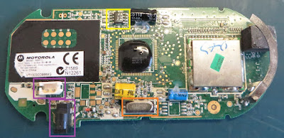 |
| Motorola MBP11 Receiver Circuit Board |
Connectors shown by the purple box may come in handy if the battery or external DC 6 V plug pack were used for another purpose.
Out of curiosity the metal can on the castellated RF board was removed.
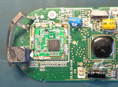 |
| Under the RF Can on the MBP11 Receiver Circuit Board |
Under the metal can was an RF chip, DE 19RF 19CNC, from a chip manufacturer called DSP Group. No immediate datasheet could be located for the chip.
Although the RF chip may not be worth salvaging, the implementation behind the castellated daughterboard is a good example of what can be achieved especially with RF.
There are a few takeaways for new circuit board designers attempting castellated boards including items such as the castellated pad spacing, RF shielding and component placement. As an example, shown by the red box in the image below, the power rail (one side) was decoupled on the main circuit board immediately after the via, then at the RF chip itself.
 |
| Decoupled Power Highlighted for Receiver Castellated Circuit Board |
There were seven LED's on the rear of the circuit board that could also be salvaged. Five LED's provided visual feedback for the sound level detected and the remaining indicating connectivity and power. Worth salvaging just for prototype boards.
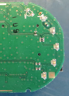 |
| LED's on MBP11 Receiver Circuit Board |
Transmitter Unit
Similar to the receiver unit, the transmitter circuit board was held in position were two additional plastic screws.
The same ‘blob’ solution and RF in a metal can was present on the transmitter board with no castellated circuit board.
The orange box showed the same 13.842 MHz surface mount crystal as the receiver and the yellow box shows the same FRAM device.
Identified by the purple box was the power connector jack.
 |
| Motorola MBP11 Transmitter Circuit Board |
Highlighted by the black box, the solitary surface mount capacitor. Manufacturer unknown.
Additionally, a linear regulator was present on the transmitter. The red box shows the LM1117. This device could be salvaged also.
The metal can was removed to show the same RF chip as the receiver unit, DE 19RF 19CNC.
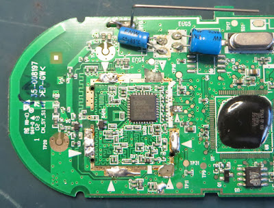 |
| Under the RF Can on the MBP11 Transmitter Circuit Board |
For both boards, the leaded electrolytic capacitors showed no signs of wear and could be salvaged if needed. All manufacturers of these electrolytic capacitors are not well known. However, some devices are rated to 105°C. Similarly, there are dozens of passive components on the board that could be pried off if required.
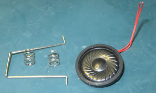
There were additional items such as the PCB mount microphone, external speaker, metal clip and springs that could come in useful for a variety of jobs.
Final Thoughts
There were further items to keep in mind regarding the technology used by these circuit boards such as the gratuitous use of test points, the practical use of via stitching in the RF area and associated power traces.
One item of caution however was the lack of Lead-Free marking on the circuit boards. For the intended target market of the Motorola MBP11, Lead-free would be no less than expected. However, as Lead-free was not noted on the circuit boards, for those salvaging from this or any such device, the appropriate preventatives should be taken.

No comments:
Post a Comment