Showing posts with label repair. Show all posts

Saturday, 24 February 2024

CTEK MXS 5.0 Pushbutton Switch Replacement

Introduction
This blog follows the process of replacing a faulty mode switch on a CTEK MXS 5.0 battery charger. The symptom of failure was no change in the mode when the mode button was pressed.

CTEK MXS 5.0 Charger
 
Repair Process

With no screws located on the charger case for servicing, YouTube was consulted on methods to open the charger.

For this charger model, the case is a two-part build. The sealing mechanism between the two cases (seam) appeared to be a glue or a plastic weld. The plastic seam was cracked by placing a flat blade (wide) screwdriver on the seam and striking the rear of the screwdriver with a mallet. The break in the plastic was, however, not entirely clean.

CTEK MXS 5.0 Open Case

On separating the case halves, the plastic base of the charger contains what appeared to be some type of isolator.

CTEK MXS 5.0 Case Bottom

CTEK MXS 5.0 Case Lid

To allow access to the charger circuit board, the cable glands at either end had to be removed. As pictured in the image below, one of the glands has an indent for a thermistor or possibly a thermal fuse.
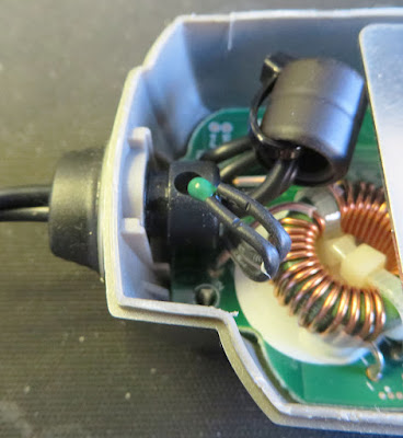
MXS 5.0 Device in Cable Gland

With the board unseated and flipped over, the logic devices, controllers, processor and switch were visible.

CTEK MXS 5.0 Circuit Board

Possibly to prevent damage to the decal, the membrane switch has a plastic cap fitted.

CTEK MXS 5.0 Circuit Board Switch Cap Off

As the pushbutton switch manufacturer and model were unknown, a similar surface mount switch was used. 

For readers preferring to locate an exact pushbutton replacement, the switch body is 6 x 6 mm with a height of 4 mm. The switch plunger height from the switch body is approximately 2.7 mm. The top of the tapered shaft is 3.45 mm. The top of the switch shaft is the side pressed into the button cap.

CTEK MXS 5.0 Factory and Replacement Switch

The plunger height of the replacement switch was manually reduced with a pair of side cutters.

After fitting the replacement switch to the circuit board, the charger was powered and the button operation was tested. The switch cap was then fitted.

CTEK MXS 5.0 with New Switch

Reassembly
The circuit board was moved into position and realigned to fit into the charger's plastic lid.

During the reassembly process, the electronic protection device was reinserted into the cable gland.
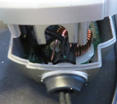
CTEK MXS 5.0 Protrusions for Cable Gland

When the two halves of the charger case were pushed together, the two U-shaped plastic protrusions on the plastic base locked the cable glands in position.

Lastly, to permanently join the halves of the charger case, glue was applied to the seams near the cable glands. For readers using the charger in a high moisture or damp environment, fully sealing the seam of the charger is highly recommended.

CTEK MXS 5.0 Charging Battery


Saturday, 15 January 2022

PSU Repair JT-DC12C5A

Summary
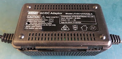
This blog details the repair of a JT-DC12C5A(II)-A switch-mode power supply.

JT-DC12C5A Power Supply
 
Details
The switch mode power supply displayed above had been operating under high load for an extended period before failure. After failure, the DC 12 V output had reduced to less than DC 2 V.

Disassembly
Note: For repair to any AC 240 V equipment, due care and attention should be taken before undertaking service work or repairs. Unplug equipment before performing repairs!

Four plastic clips are integrated into the housing and one plastic screw hold the two-piece enclosure together.

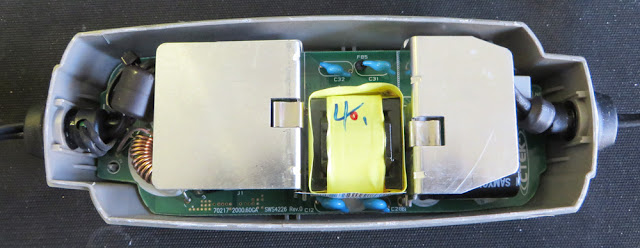
After prying the case apart, the power supply circuit board was attached to the enclosure base plate.

JT-DC12C5A Circuit Board

Servicing
A quick visual inspection of the board did not identify any burnt or charred sections on the PCB. The mains fuse continuity was good.

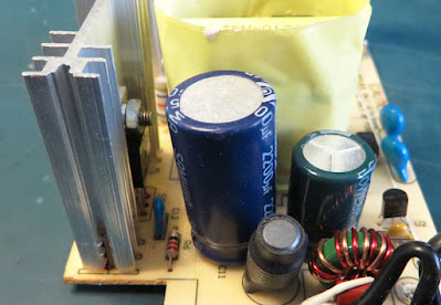
A slight bulge was noticed in one of the electrolytic capacitors located on the DC output stage. As shown in the image below, the top portion of the leftmost electrolytic capacitor is bowed upwards.

JT-DC12C5A Bulged Capacitor

The suspect capacitor was unsoldered from the power supply PCB and checked with a capacitance meter. The measured capacitance was 1 nF where the capacity listed on the case was 470 uF.

JT-DC12C5A Replaced Capacitor

A capacitor with a larger capacity of 2200 uF and the same working voltage was fitted to the circuit board.

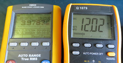
The unit was powered and a 2 A load was fitted to the output. Measuring the output voltage with the load was approximately DC 12.1 V.

JT-DC12C5A Output Load Test Measurements

The unit was reassembled and another load test was conducted at around 4 A. Operation was verified by measuring the output voltage, approximately DC 12 V.

Summary
As far as power supply circuit boards repairs rate, this was uncomplicated. However, the change to the output capacitor was made to address possible ripple currents in the output that may have damaged the smaller capacitor. As always, the component specifications should be verified before replacing in any repair.

Sunday, 26 September 2021

Micron Soldering Station Clean and Repair (T2440)

Summary
This blog covers the cleanup and minor repairs to an original Altronics (T2440) 60 W Micron temperature controllable soldering station.

Repaired and Cleaned Micron Soldering Station

Details
Purchased many years ago, the only repair or maintenance performed on the soldering station has been the replacement of the soldering iron element.

Since some of the plastic insulation around the mains power and handpiece cables was looking neglected, it was decided to perform a routine cleanup and repair of the unit.

Micron 60 W Soldering Station

Following the removal of loose dirt, the soldering station was disassembled. Four plastic screws secured the lid on the soldering station. Three plastic screws secured the heating element in the handpiece.

Disassembled Micron Soldering Station

The damaged cable from the soldering iron handpiece was cut off at the entry point into the soldering station.

Damaged Cable Entry Points
 
Isopropyl alcohol was used to clean the outside of the handpiece and connecting cable. The black plastic at the entry of the handpiece had become brittle and was replaced with two layers of black heat shrink.

Heater Element and Cable

Both the soldering element barrel cover and soldering tip were polished using a light cutting compound on a buffing wheel.

Heater Barrel Cover (Before)

Heater Barrel Cover (After)

Soldering Tip (Before)

Soldering Tip (After)
 
A bath of white vinegar (5 % solution) was used to clean the top case and soldering iron stand. These items were left to soak overnight.
 
Replacement of the black plastic around the handpiece cable was again made with black heat shrink.


Repaired Soldering Handpiece

The repaired handpiece was wired back into the soldering station.

Soldering Station Control Board

For the main cable, this was replaced with a newer style plug. Black heat shrink was fitted around the main cable at the entry point into the soldering station.

Replacement Mains Plug

The mains plug and cable were rewired into the station. As with any mains wiring the typical disclaimers and directions apply; be careful!

Rewired Mains Connection

 
Any remaining small items were firstly cleaned in an ultrasonic bath which was followed up with a liberal application of Isopropyl.
Large items such as the yellow/cream cover for the soldering station required hand cleaning with a general-purpose paste type liquid cleaner. This was required to remove ingrain flux, dirt or other burnt miscellanea.

The soldering station was reassembled and tested.

Operating Soldering Station

Sunday, 28 February 2021

LED Downlight Repair LD-18000R

Summary
This blog details the repair of a downlight (Model LD-18000R) with the replacement of the LED chip and the creation of a new LED retaining clip.

Fault Symptoms
Following several days of flickering, the LED in the downlight failed. Only a portion of the full light output was produced. Shown below is the downlight fully powered.

LED Downlight Failure - Low Output

Downlight Disassembly
With the LED disconnected from the LED driver, the rear plastic plate of the LED was opened to allow access to the cabling.

LED Downlight Rear Plate Fitted

LED Downlight Rear Plate Removed

The two screws allowing pivoting of the downlight in the base were removed. This step was not an essential step for repair as the metal retaining ring was screwed directly onto the aluminium heatsink.

LED Downlight Base Removed

The retaining ring was unscrewed from the aluminium heatsink to access the reflector.

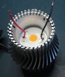
LED Downlight Reflector in Heatsink
LED Downlight Reflector in Heastink

The reflector was set in place with a small amount of clear silicone. Using gentle prying the reflector was removed without damage.

LED Downlight Reflector

While inspecting the LED fitted to the heatsink, a crack in the plastic retaining clip was noticed. It was not known if equal pressure was applied LED. The capture below shows a hairline crack in the plastic near the top left countersunk screw hole.

LED Retaining Clip - Cracked

Replacement LED
To verify failure of the LED, the LED was powered using a benchtop power supply with approximately DC 32 V. Only a portion of the LED is illuminated in the capture below.

Damaged CREE LED
Damaged CREE LED

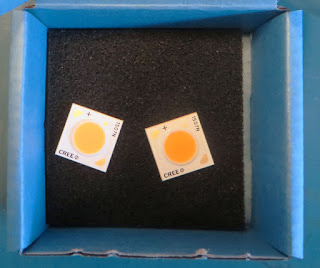
The 36 V Cree LED was marked as a CXA1507N which specifications of a colour temperature near 5000K (cool). Replacement CREE LED’s with a 3000K (warm) temperature were selected due to availability.

Replacement CREE LED's

Repairing the plastic LED retaining clip was an option however for longevity a new holder was created using a spare Printed Circuit Board (PCB). For the board used in this blog, the PCB was 1.6 mm thick, FR4 with a temperature grade (TG) 140 Celsius.

LED Retaining Clip on PCB

The outline of the plastic retaining clip was traced with a permanent marker onto the PCB.

LED Retaining Clip Tracing on PCB

Below is the PCB, drilled and shaped then placed against the CREE LED for verification.

Shaped Replacement LED Retaining Clip

Due to the PCB sitting physically higher than the previous plastic clip, new longer self-tapping screws were required. The longer screws would hold the PCB and LED to the aluminium heatsink. 

The replacement self-tapping screws were slightly larger than the previous screws meaning these needed to be cut into the aluminium block.

New Self Tappers for LED Heatsink

 
Isopropyl alcohol was used to remove the old heatsink paste and aluminium swarf. 

The positive and negative connections were soldered to the CREE LED. New heatsink paste was then applied lavishly to the rear of the LED.

Replacement CREE LED with Heatsink Paste

The replacement LED holder was deburred, cleaned, fitted then screwed down to the heatsink.

CREE LED with Replacement LED Holder

A brief power-up test was made to ensure the operation of the LED before reassembly.

Replacement CREE LED Test
  

Reassembly
For reassembly of the downlight, the plastic cover was fitted back to the aluminium heatsink.

LED Downlight Rear Plate Replaced

New white silicone was applied around the edge of the heatsink before the reflector was fitted.

Threaded LED Aluminium Heatsink

The base and retaining ring were assembled then the aluminium heatsink screwed into the ring.

Reassembled LED Downlight

As a final verification of operability, the LED was connected to the LED driver for testing.

Final Thoughts
The cost to replace each CREE LED in the set was less than USD 5.

For the faulty downlight, workshop time was required to create a replacement LED holder. Similar downlights did not have damaged LED holders.
 

Second CREE Downlight

Taking into account the cost of the LED and workshop materials, the repair cost was less than a new downlight. Furthermore, because the downlights were less than three years old, replacement of the LED’s appeared a reasonable investment. 

If the downlights were several years old, purchasing the replacement LED’s may become an issue. The remaining life of the LED driver would also need to be considered carefully before performing the repair.