Summary
This blog follows a previous post where the concept for a supply voltage interruption tester (unit) was validated.
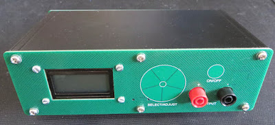
In this blog, the design was formalised by implementing the design on circuit boards using available electronic components. The alternate design supports operating voltages from DC 8 V to 60 V at 2.5 A.
 |
| Voltage Interruption Tester Prototype |
The design goal was to create a cost-effective unit that would provide indicative testing for Section 4.3.2.2 Supply Voltage Interruptions of the standard IEC 61496-1. The testing is indicative because this units is not an IEC qualified unit.
Two external power supplies supply the voltages that are switched by the unit to generate the required output waveforms.
In addition to the standard IEC tests, two additional tests were added; one for generating repetitive mains frequency noise (50 Hz) and the second for testing diodes such as Transient (TVS).
 |
| Example Output Waveform from Voltage Interruption Tester |
Editing the project source could yield additional or completely new tests.
Hardware Overview
Three circuit boards (PCB) were created. These consisted of a front, rear and internal PCB. For ease of use on the bench, the design was made to suit a small aluminium enclosure. The two boards containing electronic devices detailed below.
 |
| Power PCB Prototype (Top Side) |
The first board, labelled the power board, contained a DC 3.3V regulator with an operating range of DC 4 to 60 V, high side drivers, pluggable power banana connectors and an optional USB interface. The high side driver operating voltage is DC 8 to 60V.
 |
| Power PCB Prototype (Bottom Side) |
The front PCB was also purposed as the unit's panel. This board contained a Cypress microcontroller and a two-line LCD.
 |
| Display PCB Prototype (Bottom Side) |
Buttons were implemented on the PCB using the Cypress Capsense interface.
 |
| Display PCB Prototype (Top Side) |
Power PCB
The power PCB was created as a double-sided board so that the two high side switches (IPS160H) could take advantage of heat dissipation to the aluminium case if needed. Signals from the high-side switches were provided to the microcontroller although monitoring was not implemented at this time.
PCB mount banana plugs provided the connections for the dual supply inputs and voltage interruption tester output.
Powering of the microcontroller and LCD on the display PCB was realised using a DC 3.3 V wide operating range DC-DC switchmode (LMR16006XD). The switchmode will begin operating with an input voltage of 3.6 V which may be useful for high side switches with a lower operating voltage.
Debug and diagnostic feedback were provided through an optional USB interface.
A resistor population option allows for the selection of the switchmode supply source. This could either be input voltage 1, 2 or the optional USB.
Display PCB
Contained on the display PCB were the microcontroller and two-line LCD.
 |
| Prototype Supply Interruption Tester LCD |
An interface for the operator was achieved using PSoC Capsense buttons. Capsense signals were interfaced to the Cypress microcontroller providing a five-element radial slider and an On/Off button. The cross-hatching pattern seen on the PCB significantly helps with the Capsense operation.
Rear PCB
There were no components mounted on the rear PCB however the front and rear PCBs used the silkscreen to provide the relevant operational information.
Continued in Part 3


No comments:
Post a Comment