Introduction
This blog continues from part 4 and finalised the supply voltage interruption tester (unit) post.
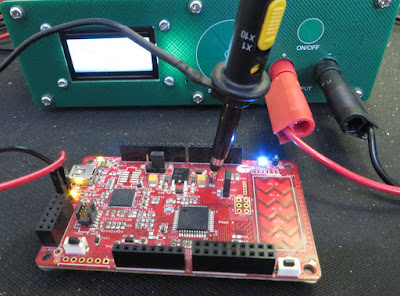
Covered in this blog is an interruption test applied to a PSoC development board. The test setup consisted of a Rigol DP832, the Interruption tester prototype and the PSoC development board part CY8CKIT-042.
 |
| Interruption Test Setup Using PSoC Development Board |
This post also provides the source and Gerber files for the interruption tester project.
Practical Interruption Test
Disclaimer - The interruption test performed on the Cypress PSoC development board was performed for the sole purpose of measurement and testing only. The PSoC development board does not claim conformance with the test conducted.
Only interruption test 1 was performed because the operating voltage of the development board was stated as DC 5 – 12 V and the minimum operating voltage for the interruption tester output drivers is DC 8 V. Test 2 and 3 require half the supply voltage which was not practical.
For the program operating on the PSoC board, two outputs of a PWM block were used to separately toggle the onboard bi-colour LED.
When interruption test 1 was enabled, the 3.3 V supply was interrupted which resulted in the processor resetting. This is evident by the irregular operation of the bi-colour LED.
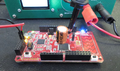
To resolve the issue caused by the dips in the supply rail, a 100 uF electrolytic capacitor was connected across the development board supply.
The two images below show a capture of the 3.3 V supply before and after the 100 uF capacitor was added to the development board.
 |
| Capture of Supply Rail During Interruption Test |
 |
| Capture of Supply Rail During Interruption Test with Additional Capacitor |
Shown in the image below is the location where the additional 100 uF capacitor was added to the development board.
Interruption Test Setup PSoC Development Board with Capacitor
While this test is straightforward on simple hardware, it shows the basic process behind interruption testing.
Final Comments
This series of blog posts focused on an overall view of the hardware design for the power supply interruption tester. While not every aspect of the design process was covered in detail, design files have been provided in the Downloads section to assist those interested in producing a similar project.
Downloads
Listed below are the PSoC Creator project, Gerber and BOM files for the Interruption Tester project. This project is supplied as shown in this blog (Posts 1 to 5).
 |
| Display Schematic and BOM |
 |
| Display Gerber and NC Drill |
 |
| Driver Schematic and BOM |
 |
| Driver Gerber and NC Drill |
 |
| Rear Panel Gerber and NC Drill |
 |
| PSoC Creator Project (Complete Archived) |


No comments:
Post a Comment