Introduction
This blog shows a piezo transducer's audible response to square waves. Measurements were performed using the software Friture with an external microphone.
 |
| Piezo Transducer |
Background
Following an incorrect delivery of a piezo transducer instead of a piezo sounder, it was fascinating to determine how the device would respond different frequencies.
Test Device
A piezo sounder is a device containing the piezo element and related drive circuitry. The drive circuitry generates the necessary signal to drive the piezo element at a specific frequency.
The piezo transducer (piezo element) tested in this blog was a part (ABT-414-RC) that specified the external drive at a certain frequency.
The specifications for the transducer are replicated below from the datasheet.
 |
| ABT-414-RC Transducer Specifications |
Testing
To measure the response of the transducer, a function generator was connected directly to the piezo. The function generator settings were made for a square wave at 0 - 3 V pk with a 50 % duty.
 |
| Image of Test Setup |
Measuring the transducer sound output was performed using the software package Friture. Friture is an open-source easy-to-navigate real-time audio analyser.
 |
| About Friture |
Friture was configured with the settings displayed below, A weighting for the measurements.
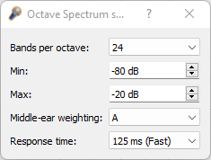 |
| Friture Settings |
The microphone for measurement was a Thronmax MDrill One Pro configured for cardioid mode.
Measurements (dB) were performed at 50 cm instead of the usual distance of 100 cm. These measurements were indicative.
Frequencies between 1 kHz and 4 kHz were set on the function generator, with measured values taken from Friture. Pictured below are the plotted results taken at 50 cm spacing between the piezo and microphone.
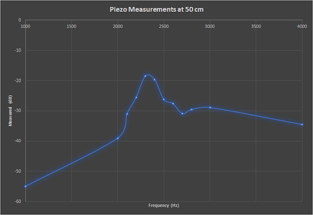 |
| Plot of Measurements vs Frequency for ABT-414-RC |
The operation of the function generator was then changed from a single frequency to a sweep. Frequencies were swept between 1 kHz and 6 kHz over a period of 100 ms.
In the screen capture below from Friture, the first frequency peak at 2.4 kHz is seen first. There was a second resonant measurement at approximately 5 kHz.
 |
| Plot from Friture for ABT-414-RC Frequency Sweep |
The sweep response above shows that the drive frequency for the piezo transducer can vary by a more than 100 Hz with minor reduction in output level.
Lastly, the function generator output frequency was set to 2.4 kHz. The measurement from Friture is displayed blow.
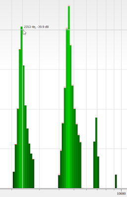 |
| Piezo Measurement at 2.4 kHz |
Limiting Piezo Voltage
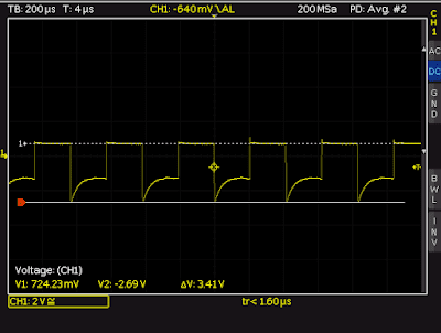
To limit voltages seen by the driving source, a device such as a general-purpose diode is recommended across the terminals of the piezo. The two oscilloscope captures below show the effect on the waveform with and without a diode across the transducer.
When measuring the sound level with the microphone, the difference in measurements for a frequency of 2.4 kHz was less than 2 dB with and without a diode fitted.
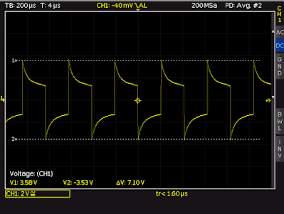 |
| Waveform at Piezo Transducer |
 |
| Waveform at Piezo Transducer with Parallel Diode |
Summary
A piezo transducer can readily replace a piezo sounder however, implementation will depend on the hardware utilised to drive the piezo. Circuit protection should also be reviewed as part of the standard impact analysis.

No comments:
Post a Comment