Introduction
This blog follows the process of replacing a faulty mode switch on a CTEK MXS 5.0 battery charger. The symptom of failure was no change in the mode when the mode button was pressed.
 |
| CTEK MXS 5.0 Charger |
Repair Process
With no screws located on the charger case for servicing, YouTube was consulted on methods to open the charger.
For this charger model, the case is a two-part build. The sealing mechanism between the two cases (seam) appeared to be a glue or a plastic weld. The plastic seam was cracked by placing a flat blade (wide) screwdriver on the seam and striking the rear of the screwdriver with a mallet. The break in the plastic was, however, not entirely clean.
 |
| CTEK MXS 5.0 Open Case |
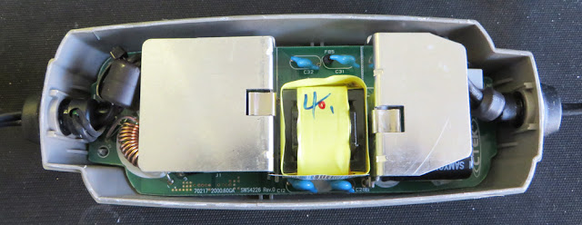
On separating the case halves, the plastic base of the charger contains what appeared to be some type of isolator.
 | |
| CTEK MXS 5.0 Case Bottom |
 |
| CTEK MXS 5.0 Case Lid |
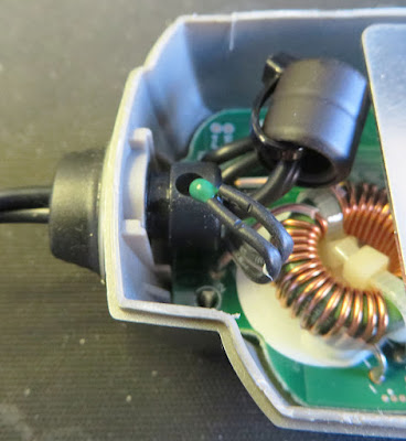
To allow access to the charger circuit board, the cable glands at either end had to be removed. As pictured in the image below, one of the glands has an indent for a thermistor or possibly a thermal fuse.
 |
| MXS 5.0 Device in Cable Gland |
With the board unseated and flipped over, the logic devices, controllers, processor and switch were visible.
 |
| CTEK MXS 5.0 Circuit Board |
Possibly to prevent damage to the decal, the membrane switch has a plastic cap fitted.
 |
| CTEK MXS 5.0 Circuit Board Switch Cap Off |
As the pushbutton switch manufacturer and model were unknown, a similar surface mount switch was used.
For readers preferring to locate an exact pushbutton replacement, the switch body is 6 x 6 mm with a height of 4 mm. The switch plunger height from the switch body is approximately 2.7 mm. The top of the tapered shaft is 3.45 mm. The top of the switch shaft is the side pressed into the button cap.
 |
| CTEK MXS 5.0 Factory and Replacement Switch |
The plunger height of the replacement switch was manually reduced with a pair of side cutters.
After fitting the replacement switch to the circuit board, the charger was powered and the button operation was tested. The switch cap was then fitted.
 |
| CTEK MXS 5.0 with New Switch |
The circuit board was moved into position and realigned to fit into the charger's plastic lid.
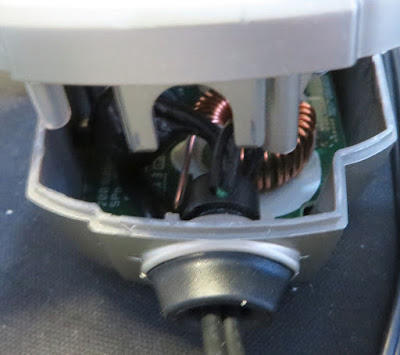
During the reassembly process, the electronic protection device was reinserted into the cable gland.
 |
| CTEK MXS 5.0 Protrusions for Cable Gland |
When the two halves of the charger case were pushed together, the two U-shaped plastic protrusions on the plastic base locked the cable glands in position.
Lastly, to permanently join the halves of the charger case, glue was applied to the seams near the cable glands. For readers using the charger in a high moisture or damp environment, fully sealing the seam of the charger is highly recommended.
 |
| CTEK MXS 5.0 Charging Battery |
