Introduction
This blog continues from Part 2 of the ‘Wi-Fi-controlled
rocket launcher’. In this blog, the software changes to suit the ESP8266
are mentioned. Additionally, a mechanical 'proof of concept' for the rocket
launcher is shown using a 3D-printed case.

|
| Bench Test of Rocket Launcher |
Code Change Summary
In the earlier version of the model rocket launcher design, a PSoC
microcontroller with Bluetooth was selected for communications. When
moving to the ESP8266, the Bluetooth communications interface was changed
to a Wi-Fi interface. Using a Wi-Fi interface simplified the design when compared to developing in Android Studio.
To
support a broader audience using the ESP8266, it was decided to
perform software development using the Arduino platform.
/** *****************************************************************************
* @file   main.c
* @version 1.0b
* @date 10/02/2024
* @brief
* 01/03/2023  Moved code from original PSoC version into Arduino
* 13/01/2024  Changed code operation, updated launch state machine
* 24/01/2024  Client connection issues noted during testing
* 10/02/2024  Code cleanup. Changed deprecated server.available() to server.accept()
****************************************************************************** */

#if !defined(ESP8266)
  #error For ESP8266. Check
      Tools->Board setting
#endif

/*_TIMERINTERRUPT_LOGLEVEL_ from 0 to 4 */
#define TIMER_INTERRUPT_DEBUG         1
#define _TIMERINTERRUPT_LOGLEVEL_     1
#define ENABLE_DEBUG_PRINTS           true
Most parts of the original code from the PSoC, including the launcher state machine, were either updated or rewritten. Code changes were needed for the ESP and targeted toward proper encapsulation.
ITimer.attachInterruptInterval(TIMER_INTERVAL_MS * 1000,TimerHandler); /* 10 ms system timer */
Snippets and
libraries from the Arduino community were included in the new launcher
code. Specifically, credit goes to
Khoi Hoang for Timer Interrupt
examples and
Martyn Currey for ESP Wi-Fi
implementation.
How Software Was Developed
The code was developed using the Arduino IDE. Initial testing for the ESP code was performed using a
Windows laptop for the Wi-Fi connection primarily to test the webpage interface. Testing subsequently progress to
an Android phone.
Shown in the image below is the first rocket launcher web page. Additional information such as battery voltage and launch state may be included on the web page in later updates.

|
|
Rocket Launcher Webpage |
Launcher Case
After reviewing the previous enclosure and cost, it was decided to
design a 3D-printable enclosure to house a small lead acid battery and a
control board. The lead acid battery is only temporary and will be changed to an
18650-cell(s) capable of a high-discharge current.
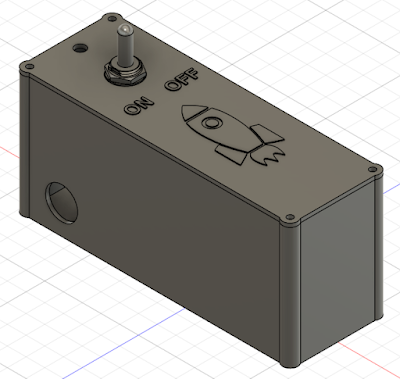
For the 3D-printed
case, two mechanical parts were drafted in Fusion 360. These parts
comprised of a base and a lid as pictured below.

|
|
Rocket Launcher Case (Fusion 360) |
Launcher Hardware Assembly
With the ESP code allowing the desired launch operation, the circuit board, wiring
and battery were assembled and added to the 3D-printed case.

|
|
Rocket Launcher Test Assembly |
During the assembly, it was noted that the pluggable circuit board headers, although simple to install and use, were expensive and consumed space. On the subsequent revision of the board, as displayed below, the pluggable headers were replaced with through-hole solder pads that suit a larger gauge wire.

|
|
Updated Launcher Board |
Additionally, the toggle switch used for controlling the power was salvaged from another project. There are no manufacturer markings on the switch to generate a Bill of Materials. More clearance was added around the toggle switch body to suit other types of toggle switches such as the model shown below.

|
|
Standard Toggle Switch |
Complete Test Assembly
For a bench test, a lamp was used as the igniter as
pictured below. A short video of the operational launcher is exampled in the video.
The next post will feature the updated launcher circuit board and field testing.
