Introduction
This brief blog details the salvageable components from the circuit boards of a mains-powered LED light baton manufactured by ATOM.
 |
| ATOM Baton Nameplate |
Attempting a Repair
When the LED baton, Atom part #AT9877, initially failed to switch ON, the initial thought was that a repair should be possible. Disassembling the unit and checking the control board revealed some damaged resistors.
 |
| Damaged Resistors on Circuit Board |
After replacing the resistors and retesting the baton, it became apparent that multiple components on the board had failed. The additional failed components included the main switching FET and, after a subsequent test, the onboard fuse. Although a repair seemed feasible, reliability was in question, so the part salvage route was instead chosen.
Parts Salvage
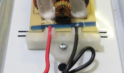
As the baton was already partially disassembled, the control board was easily removed. Two plastic holders were fitted to the ends of the board, and then those clips were fixed into the baton’s metal housing. The board mounting solution is an interesting alternative to mounting holes, which are usually included on circuit board designs.
 |
| Plastic Circuit Board End Clips |
The wires to the control circuit board were cut, and the control board assembly was removed. Remaining fitted to the baton's chassis, which could be salvaged, were solid core mains cable, the LED boards and some fixings, including terminal blocks.
Each of the two LED boards was fixed in place with seven plastic pins, as shown in the image below. The clips were removed by pushing them from the other side of the baton.
 |
| Plastic Clips Holding LED Circuit Boards to the Baton Chassis |
The 60 LEDs per board were checked using the diode test on the multimeter; both LED boards could be salvaged or kept for similar LED baton repairs.
 |
| LED Strip Markings |
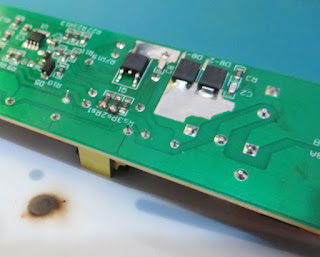
Turning attention back to the control circuit board, this was a double-sided (population) design. The control board consisted of surface mount parts on the copper (solder) side and through-hole components on the opposite side. Surface-mount parts were held to the circuit board with an epoxy adhesive, such as the Chip Quik AD1-10S or Henkel Loctite 3621, making reworking or salvaging parts difficult. The benefit for the manufacturer, however, is that this design results in a simplified process during soldering (usually reflow).
 |
| Baton Control Board - Solder Side |
If easily removed, the diodes (red box in the solder side image) can be salvaged from the solder side of the circuit board. The two larger rectifier diodes marked as US5M are from the manufacturer Suntan.
A datasheet for the main switching FET (yellow box in the solder side image) could not be sourced, and the part number for the 8-pin controller was not easily readable.
 |
| Baton Control Board - Top Side |
Reviewing the through-hole component side of the control board, the combination of six inductors and chokes (purple boxes in top side image) could be salvaged with minimal risk of damage.
The bridge rectifier (green box) from NextGen components, part KBP210, could be removed and tested.
The manufacturer for the majority of the electrolytic capacitors (red boxes) was Axboom. The three large mains rated 47 uf 350 V devices showed no signs of damage or bulging and could be salvaged.
Long or larger components, such as the capacitors on this board, are secured with white glue or silicone, although this material can easily be cut off.
There is a safety capacitor (blue box) on the board marked with JNC, JY332M; a datasheet could not be found. This appears to be a 400 V AC 0.0033uF Y5U capacitor, and although the Y5U specification drifts when the temperature changes (image below), the part may be useful for other designs or repairs.
 |
| Example - Y5U Safety Capacitor vs Temperature |
The varistor (black box) on the AC supply appears to be from SONGLONG LISHANG, part 07D471K. This varistor could be tested and used for repairs.
Although the fuse was damaged on this baton, Littelfuse TE5® 392 series markings T1AL250V, it could be salvaged on a working control board.
