
As mentioned in a prior blog involving the Beta Layout V2 Reflow Controller, the on-board RS232 can be removed and USB added using an adaptor such as the Adafruit - CP2104.
Hardware Required
Beta Layout V2 Controller
Adafruit USB to TTL Adaptor #CP2104
 |
| Beta Layout V2 with USB |
Beta Layout V2 Controller
Adafruit USB to TTL Adaptor #CP2104
1 x 1k 0805 resistor
2 x M2.5 plastic screws
2 x M3 x 15mm bolts
2 x M3 star washers
2 x M3 flat washers
2 x M3 nuts
1 x plastic L bracket (home made)
3 x small lengths of hookup wire
2 x M2.5 plastic screws
2 x M3 x 15mm bolts
2 x M3 star washers
2 x M3 flat washers
2 x M3 nuts
1 x plastic L bracket (home made)
3 x small lengths of hookup wire
Opening the Controller
As detailed on a previous blog the Beta Layout case does not use fixing to hold the two part enclosure together. Instead there are a pair of opposing plastic clips on the lid and base, concealed by the ventilation holes, which were released using a flat blade screwdriver to gain access to the controller.
 |
| Beta Layout V2 Controller |
There are only a handful of components associated with the existing TTL to RS232 driver (MAX232) and these components are all surface mount capacitors for the charge pump or supply decoupling. For more details on the RS232 driver see the Maxim datasheet - MAX232.
In the image below the components to be removed are circled in RED.
Mounting the Adafruit Board
In the image below the components to be removed are circled in RED.
 |
| Logic Board RS232 Driver |
To unsolder the MAX232 driver it was easier to unscrew the logic board so that the board could be worked on directly. While the 10 way header for the serial port can be unplugged, the Thermocouple wires are soldered directly to the logic board so the connector must be removed from the plastic panel.
To remove the Thermocouple connector from the panel of the unit, the bolt connected to the metal plate is first unscrewed, then the bolt holding the Thermocouple connector together is removed. This allows the connector to come apart allowing the logic board to be removed from the unit.
One of the easiest methods to remove the MAX232 driver is to use two soldering irons, unless you have a tool for your soldering iron that can remove SOIC packages! Alternatively a set of side cutters to chop the legs off the driver and solder wick to clean up the mess works wonders if there is no interest in saving the driver.
To remove the Thermocouple connector from the panel of the unit, the bolt connected to the metal plate is first unscrewed, then the bolt holding the Thermocouple connector together is removed. This allows the connector to come apart allowing the logic board to be removed from the unit.
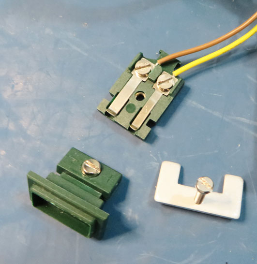 |
| Thermocouple Connector Disassembly |
Removing the RS232 Driver
 |
| Logic Board RS232 Driver Removed |
In the image above the driver and four charge pump capacitors were removed. The capacitor to the lower left of the MAX232, for the power supply decoupling, was left on the PCB. For people choosing to use another flavour of USB to TTL adaptor they may find that external 5V power is required. This capacitor, even though small, may be able to provide some minimal power supply decoupling for an alternative adaptor board.
The Adafruit adaptor board which was used in this upgrade, is bus powered, so this decoupling capacitor is not used and could be removed. Below is an image of the changes to the logic board. These are explained below.
 |
| Logic Board with Adafruit USB Adaptor |
Logic Board Changes
For the image above the changes listed below were made.
- Bridge the transmit lines on the MAX232 footprint.
As shown in the image below there are two pins which need to be linked 'shorted' together. These pins are actually pin numbers 7 and 10 on the actual MAX232 transceiver.
Bridge MAX232 Transmit Lines - Connect a 1k resistor between the receiver lines on the MAX232 footprint.
Since the receiver line from the USB to TTL converter can provide enough power to supply the ATMEGA a current limiting resistor was added between the boards. The rail to rail steering diodes inside the ATMEGA cause this phenomenon. See this EEVBlog #831 Episode for a detailed description on YouTube.
Add 1K Resistor Receive Line The resistor is fitted between pin 12 of the MAX232 and the via directly adjacent to the right between the transceiver pads. As the board via's are untented the resistor can be soldered directly to the via.
- Connect TTL transmit, receive and 0VDC to the Adafruit adaptor.
The original transmit and receive lines on the PCB header were reused for connection to the USB to TTL converter. As shown in the image below the three connections are all made to the inside pins on the header.
USB to TTL Connections The transmit connection is the TXD pin, receive the RXD pin and 0VDC is the GND pin on the Adafruit USB to TTL adaptor.


Mounting the Adafruit Board
To mount the Adafruit board a custom L bracket was made from plastic and fashioned to cover the old 9 pin serial connector cut out.
 |
| Adafruit USB to TTL L-Adaptor |
Since there are only two mounting holes (ID 2.5mm) on the Adafruit board a pair of 2.5mm self-tappers were used to hold the board in position.
 |
| Mounted Adafruit Board |
To hold the L-bracket in position against the panel of the Beta Layout unit, a pair of 3 x 15mm bolts were used with the usual star washers and nuts on the rear and M3 flats against the outside of the units panel.
 |
| Mounted Adafruit in Case |
As a dry run the unit was assembled without fixing the power board down to check the clearances.
 |
| Final Mounting of USB to TTL Adaptor |
Testing the Adafruit Board
To be prudent the USB was connected to a PC running TeraTerm. The unit was powered with the Thermocouple fitted into the connector.
Running on Windows 7 the drivers installed automatically for the Silicon Labs USB controller. Below is a capture of the USB connection running at 9600 baud.
To be prudent the USB was connected to a PC running TeraTerm. The unit was powered with the Thermocouple fitted into the connector.
 |
| USB to TTL Converter in Device Manager |
 |
| TeraTerm - USB to Beta Layout V2 |
The USB to TTL adaptor was working as expected and so the Beta Layout unit was reassembled by fixing down the power board.
 |
| Power Board Fixings Under Connectors |
Final Mounting
Note that one of the plastic screws to hold down the power board was located underneath the mounted Thermocouple connector. The second screw was located on the opposite end of the power board underneath the Adafruit PCB.
Should repairs need to be performed on the power board the Thermocouple connector and USB board would need to be removed to gain access to the unit.
No comments:
Post a Comment