Introduction
This blog follows on from a previous post relating to WiFi communication with an EPEVER MPPT. In this post, a DIN rail mount adaptor was created to power the Elfin EW11A (WiFi to RS485) device.
 |
| EPEVER MPPT to Elfin EW11A Adaptor |
Wiring
In a previous post, the connection to an EPEVER MPPT was tested using an Elfin EW11A that was set up for station-mode WiFi operation. The test wiring described in this post was clumsy so a permanent fixture was designed.
DIN Rail Mount Solution
The connections required for the circuit board between the MPPT and EW11A were already established and tested. To power EW11A, a Texas Instruments DC-DC buck converter was selected.
To mount the circuit board containing the aforementioned parts and rather than spinning up a 3D printed part, Adafruit’s DIN rail mount was used.
Schematic
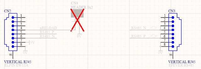
The RS485 schematic connection between the MPPT and EW11A using RJ45 connectors is shown below.
 |
| Circuit Board Connections for EPEVER MPPT to Elfin EW11A |
In the power supply circuit shown below, a reverse polarity protection diode is at the front end of the design. Following the polarity diode is an optional transient diode (TVS) clamp and PI filter. Bypassing the filter is possible using the two optional bypass resistors which were added in revision 1 of the circuit board. Powering the EW11A is a DC-DC buck converter, notably the Texas Instruments LMR14203; no linear regulators here. At the time of writing the lead time of TI regulators exceeds a year so some equivalents could be the LMR16006X, LMR16006Y or MP2451DJ; these alternatives should be reviewed for compatibility.
 |
| Circuit Board Connections for Elfin EW11A Power Supply |
For the sundry items on the board, a power LED was included but to conserve power this device could be unpopulated or the series current limiting resistor increased.
To reset the EW11A, a pair of circuit board pins were provided on the circuit board. Shorting the two pins provided on the circuit board will perform the reset.
Circuit Board (PCB)
The board shape was designed using the dimensions shown on the DIN holder datasheet (Adafruit website). The fitment of the circuit board in the DIN holder was accurate, although the placement of components near the edge of the circuit board was tight. A larger keep-out for the components from the edge of the circuit boards was included in the next revision of the board.
 |
| EPEVER MPPT to Elfin EW11A Circuit Rev 1 Board Top Layer |
 |
| EPEVER MPPT to Elfin EW11A Circuit Board Rev 1 Bottom Layer |
Testing
The populated circuit board was powered with DC 24 V and load-tested. No temperature, climate or similar tests were performed.
With no load, the DC output voltage was 5.02 V with a quiescent current of 5 mA (LED). The output voltage dropped to 4.98 V when the EW11A was powered by the regulator. Greater than DC 6 V should be provided to the DC-DC converter for stable operation.
 |
| EPEVER MPPT to Elfin EW11A Circuit Board Rev 0 Bottom Layer |
A functional soak test of the circuit board over a 24-hours showed no issues. No dropped packets were detected by the virtual COM port application "HW Virtual Serial Port", version 3.1.2.
Downloads
Listed below are the MPPT to EW11A adaptor schematics, circuit board Gerber files and project Bill of Materials. The blank circuit boards can be made available at PCB Way using their Shared Projects option. The supplied schematic and Bill of Materials are for a fully populated circuit board.
Disclaimer: Please note that revision 0 of the the circuit board was tested in this post; no functional changes relating to the MPPT or EW11A connections were made in revision 1 of the circuit board.
 |
| Elfin to EPEVER Rev 1 Schematic |
 |
| Elfin to EPEVER Rev 1 PCB |
 |
| Elfin to EPEVER Rev 1 BOM (Full) Excel |
 |
| Elfin to EPEVER Rev 1 Gerber and NC Drill |

No comments:
Post a Comment