Showing posts with label epever. Show all posts

Saturday, 19 November 2022

EPEVER MPPT to Elfin EW11A Adaptor Circuit Board

Introduction
This blog follows on from a previous post relating to WiFi communication with an EPEVER MPPT. In this post, a DIN rail mount adaptor was created to power the Elfin EW11A (WiFi to RS485) device.

EPEVER MPPT to Elfin EW11A Adaptor

Wiring
In a previous post, the connection to an EPEVER MPPT was tested using an Elfin EW11A that was set up for station-mode WiFi operation. The test wiring described in this post was clumsy so a permanent fixture was designed.

DIN Rail Mount Solution
The connections required for the circuit board between the MPPT and EW11A were already established and tested. To power EW11A, a Texas Instruments DC-DC buck converter was selected. 

To mount the circuit board containing the aforementioned parts and rather than spinning up a 3D printed part, Adafruit’s DIN rail mount was used.

Schematic
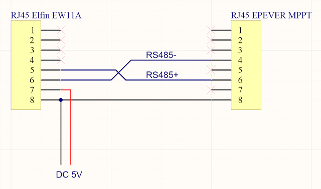
The RS485 schematic connection between the MPPT and EW11A using RJ45 connectors is shown below.
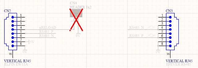
Circuit Board Connections for EPEVER MPPT to Elfin EW11A

In the power supply circuit shown below, a reverse polarity protection diode is at the front end of the design. Following the polarity diode is an optional transient diode (TVS) clamp and PI filter. Bypassing the filter is possible using the two optional bypass resistors which were added in revision 1 of the circuit board. Powering the EW11A is a DC-DC buck converter, notably the Texas Instruments LMR14203; no linear regulators here. At the time of writing the lead time of TI regulators exceeds a year so some equivalents could be the LMR16006X, LMR16006Y or MP2451DJ; these alternatives should be reviewed for compatibility.

Circuit Board Connections for Elfin EW11A Power Supply

For the sundry items on the board, a power LED was included but to conserve power this device could be unpopulated or the series current limiting resistor increased.
To reset the EW11A, a pair of circuit board pins were provided on the circuit board. Shorting the two pins provided on the circuit board will perform the reset.

Circuit Board (PCB)
The board shape was designed using the dimensions shown on the DIN holder datasheet (Adafruit website). The fitment of the circuit board in the DIN holder was accurate, although the placement of components near the edge of the circuit board was tight. A larger keep-out for the components from the edge of the circuit boards was included in the next revision of the board.

EPEVER MPPT to Elfin EW11A Circuit Rev 1 Board Top Layer

EPEVER MPPT to Elfin EW11A Circuit Board Rev 1 Bottom Layer

Testing
The populated circuit board was powered with DC 24 V and load-tested. No temperature, climate or similar tests were performed.

With no load, the DC output voltage was 5.02 V with a quiescent current of 5 mA (LED). The output voltage dropped to 4.98 V when the EW11A was powered by the regulator. Greater than DC 6 V should be provided to the DC-DC converter for stable operation.

EPEVER MPPT to Elfin EW11A Circuit Board Rev 0 Bottom Layer

A functional soak test of the circuit board over a 24-hours showed no issues. No dropped packets were detected by the virtual COM port application "HW Virtual Serial Port", version 3.1.2.

Downloads
Listed below are the MPPT to EW11A adaptor schematics, circuit board Gerber files and project Bill of Materials. The blank circuit boards can be made available at PCB Way using their Shared Projects option. The supplied schematic and Bill of Materials are for a fully populated circuit board.

Disclaimer: Please note that revision 0 of the the circuit board was tested in this post; no functional changes relating to the MPPT or EW11A connections were made in revision 1 of the circuit board.

Elfin to EPEVER Rev 1 Schematic

Elfin to EPEVER Rev 1 PCB

Elfin to EPEVER Rev 1 BOM (Full)
Elfin to EPEVER Rev 1 BOM (Full) Excel

Elfin to EPEVER Rev 1 Gerber and NC Drill

Tuesday, 8 November 2022

EPEVER MPPT to PC using RS485 or WiFi

Introduction
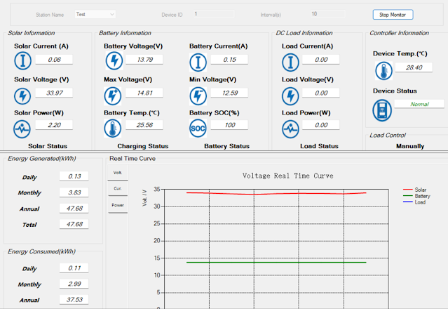
This blog provides two methods for connecting an EPEVER MPPT with RS485 capability to a Windows PC running Solar Station Monitor.

EPEVER Solar Station Monitor

Direct Connection
Direct connection utilises hardware consisting of an FTDI USB to RS485 adaptor, part USB-RS485-WE with an RJ45 male to screw terminal adaptor to connect to the EPEVER MPPT.

Details for the various connections using the FTDI adaptor are pictured below.

RS485 connections A, B and 0 V were used; no termination resistor was added to the circuit.

FDTI RS485 to EPEVER MPPT

Wired USB FTDI to RJ45 adaptor.

FDTI RS485 to RJ45 8-Way Screw Terminal for EPEVER MPPT

FTDI adaptor wiring from USB-RS485-WE manual.

USB-RS485-WE Connections (Courtesy FTDI)

 Pinout for RJ45 connector.

RJ45 Pinouts
RJ45 Pinouts (Courtesy Huawei)

There were no requirements to change the Windows setup for the FTDI adaptor. This device appears as a standard COM port. This COM port was then selectable in the EPEVER Solar Station Monitor application.

Wireless Connection
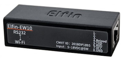
The wireless connection makes use of an Elfin EW11A. This device bridges RS485 and wireless station and or access point.

Elfin EW11A (Courtesy Hi-Flying)

Also used in the hardware solution was the optional Elfin adaptor cable. For connecting to the EPEVER MPPT, an RJ45 male to screw terminal adaptor was utilised. Since the EW11A requires DC 5 V, an further connection to a power supply is also required.


Elfin EW11A to EPEVER MPPT

Elfin EW11A to RJ45 8-Way Screw Terminal

The computer running EPEVER Solar Station Monitor required a software Ethernet to COM port bridge. The HW Virtual Serial Port application from HW-Group was used.
Side note. The EPEVER WiFi 2.4 G RJ45 A adaptor was tested separately however because WiFi Station mode was required, the EPEVER was not suitable.


Elfin EW11A Setup

This tests in this blog were geared towards verifying that wireless communications with the MPPT were practicable. The final goal was to interface the EPEVER with Home Assistant.

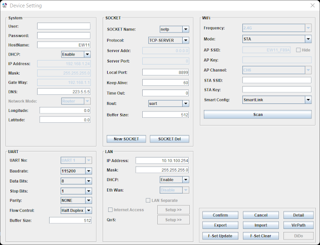
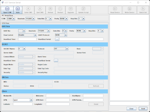
Using the I.O.T Workshop application from High-Flying, the EW11A was configured for station mode, TCP server and the port settings were configured for consistency with Home Assistant. Ethernet port number 8899 (MQTT) was used. The Comment and Application Guide from Eniris was used as the primary reference document.

Removed from the screen capture below are the login details (admin and password), wireless station ID and associated password.

EW11A Device Setup for EPEVER MPPT Using I.O.T Workshop

No UART protocol was selected. Telnet was disabled and web interface was kept enabled.

EW11A Device Detail for EPEVER MPPT Using I.O.T Workshop

The UART settings 115200, 8, N, 1 were left as default.

EW11A Serial Setup for EPEVER MPPT Using I.O.T Workshop

Virtual Serial Port
For this blog the
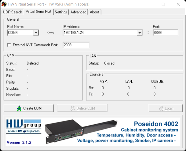
HW Virtual Serial Port application from HW-Group was used. The default configuration of the application required changes. For example, if the option Network Virtual Terminal (NVT) was enabled, communications with the EPEVER MPPT were sporadic or only specific values were received correctly. Other tools offering an Ethernet to COM virtual com port may offer similar configuration options which should be validated.

HW Virtual Serial Port Settings for EPEVER MPPT  and Elfin EW11A
HW Virtual Serial Port Settings for EPEVER MPPT and Elfin EW11A

Shown on the Virtual Serial Port page is the IP and port for the Elfin EW11A.

HW Virtual Serial Port Page for EPEVER MPPT with Elfin EW11A

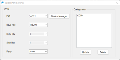
With the Elfin EW11A configured and powered, clicking Create COM in the virtual serial port application established the Ethernet link. Shortly after COM4 appeared in Windows Device Manager.

Serial Port Created Using HW Virtual Serial Port

With a connection established to the EW11A and the EPEVER MPPT, the EPEVER application could communicate with the MPPT. This was indicated by the change in counter values (Rx and Tx).

HW Virtual Serial Port Connected to EPEVER MPPT with Elfin EW11A

Solar Station Monitor
No changes were made to the setup of the EPEVER Solar Station Monitor application other than configuring the required COM port to communicate with the Virtual COM port.
The default port settings were used.

EPEVER COM Port Settings
 

After clicking Start Monitor in the application, data was exchanged within a few seconds.

The capture below was taken after sunset with the MPPT load active.

EPEVER Solar Station Monitor (Load Active)

The capture below was taken during sunlight hours.

EPEVER Solar Station Monitor (During Daylight)


For the capture below, the EPVER monitoring tool was restarted to capture the transition between load OFF and ON.

EPEVER Solar Station Monitor Graphed Data Showing Load ON

EPEVER Solar Station Monitor Graphed Data Showing Load OFF

Final Thoughts
This post offered two methods for connecting an EPEVER MPPT with a Windows PC running Solar Station Monitor application. The WiFi connection and subsequent testing using the Elfin EW11A served as preliminary work to develop a dedicated circuit board to bridge the EW11A with the EPEVER MPPT.

Thursday, 6 October 2022

EPEVER WiFi RS485 Adaptor Default IP Address from CLI

Summary
This blog briefly describes the new processor used on the EPEVER WiFi 2.4 GHz to RJ45 Adaptor (Ver 4.0) hardware. The command line interface (CLI) provided by the WiFi adaptor is also described. This interface was used to confirm the default IP address of the unit in AP (Access Point) mode was 192.168.169.2

EPEVER WiFi RS485 Adaptor (V4)

WiFi Hardware

The latest version of the EPEVER WiFi Adaptor hardware with the black plastic enclosure uses a Winner Micro W600-B800 System on Chip (Soc). Also contained on the circuit board is the serial flash required by the SoC, RS485 driver, switch mode supply and associated passive components.

Interface to SoC
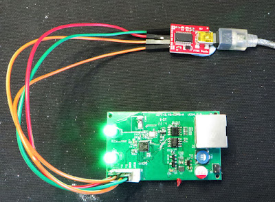
A SparkFun FTDI Basic adaptor was configured for 3.3 V and then connected to the 5-way header on the WiFi circuit board. The other side of the USB to TTL converter was connected to a PC.

EPEVER to USB Converter

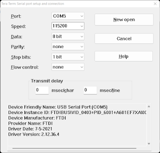
After reviewing the SoC datasheet, serial port settings of 115200, 8, N, 1 were used with a terminal program. The capture below shows the port settings for Tera Term.

Tera Term Communications Settings for EPEVER Debug

WiFi Adaptor Output Log
The output log from the WiFi adaptor SoC shows that the RT-Thread RTOS is used. There is a plethora of reading material on the RT-Thread website including the
tools required for interfacing with the SoC. These software packages were not verified in this post.

In the log shown below, the default IP address of the WiFi adaptor is listed as 192.168.169.2 with a port of 65010 for communincations to the RS485 port.

[SFUD]Warning: Read SFDP parameter header information failed. The norflash is not support JEDEC SFDP.
[SFUD]Warning: This flash device is not found or not support.
[SFUD]Warning: Read SFDP parameter header information failed. The norflash is not support JEDEC SFDP.
[SFUD]Warning: This flash device is not found or not support.
[SFUD]Error: norflash flash device is initialize fail.
[I/FAL] RT-Thread Flash Abstraction Layer (V0.4.0) initialize success.
[E/OTA] (ota_main:41) download partition is not exist, please check your configuration!
[D/OTA] (ota_main:105) jump to APP!
redirect_addr:8010100, stk_addr:20005888, len:851968

 \ | /
- RT -     Thread Operating System
 / | \     4.0.2 build Feb 25 2022
 2006 - 2019 Copyright by rt-thread team
lwIP-2.0.2 initialized!
ERROR: SPI device fl_spi not found!
[I/sal.skt] Socket Abstraction Layer initialize success.
[D/FAL] (fal_flash_init:61) Flash device |w60x_onchip | addr: 0x08000000 | len: 0x00100000 | blk_size: 0x00001000 |initialized finish.
ERROR: Flash device w25q128 not found!
[D/FAL] (fal_flash_init:61) Flash device |norflash | addr: 0x00000000 | len: 0x00000000 | blk_size: 0x00000000 |initialized finish.
[D/FAL] (fal_partition_init:176) Find the partition table on 'w60x_onchip' offse                                     t @0x0000ff88.
[I/FAL] ==================== FAL partition table ====================
[I/FAL] | name       | flash_dev   |   offset   |    length  |
[I/FAL] -------------------------------------------------------------
[I/FAL] | app        | w60x_onchip | 0x00010100 | 0x000d0000 |
[I/FAL] | easyflash  | w60x_onchip | 0x000e0100 | 0x00004000 |
[I/FAL] | filesystem | w60x_onchip | 0x000e4100 | 0x00019000 |
[I/FAL] =============================================================
[I/FAL] RT-Thread Flash Abstraction Layer (V0.3.0) initialize success.
[Flash] (packages\EasyFlash-v3.3.0\src\ef_env.c:152) ENV start address is 0x00000000, size is 8192 bytes.
[Flash] (packages\EasyFlash-v3.3.0\src\ef_env.c:821) Calculate ENV CRC32 number is 0xD6114A34.
[Flash] (packages\EasyFlash-v3.3.0\src\ef_env.c:833) Verify ENV CRC32 result is OK.
[Flash] (packages\EasyFlash-v3.3.0\src\ef_env.c:821) Calculate ENV CRC32 number is 0x78CA81B2.
[Flash] (packages\EasyFlash-v3.3.0\src\ef_env.c:833) Verify ENV CRC32 result is OK.
[Flash] EasyFlash V3.3.0 is initialize success.
[Flash] You can get the latest version on https://github.com/armink/EasyFlash .
<--------------------software: GT100WS142W600T------------------>
tls_fls_init() return 2
init MyFile obj is success.
enter InitHnjdClass() success.
ql_dev_init()=0

<-- lt_sock_para_1()  APP_NV_SYS=,ret=0. ID=00065689.MAC=202205111459122 -->
<--init0 hnjd paraments success  loraSize=0-->
Hnjd_GetImei(), imei:202205111459122;
<--init hnjd paraments success  loraSize=0-->
init gpio class success.
RT-Thread create eventUart2Recv successful
init serial class success.
init logs class success.
Hnjd_GetImei(), imei:202205111459122;
SecCount=-1,SendCount=0
COM<-- 89 D2 D4 D2 D2 D4 CF D3 D3 D3 D0 CF CB D3 D2 D2 00 D4 D4 D4 D4 D4 D4 23 1D A8 88
msh />gpio task running......
serial task2 running......
COM--> 89 D2 D4 D2 D2 D4 CF D3 D3 D3 D0 CF CB D3 D2 D2 00 D2 D4 D4 CC D4 D3 23 1D 9D 88
TEA success.
init system success.
[D/DFS] enter AP mode

[I/WLAN.dev] wlan init success
[I/WLAN.lwip] eth device init ok name:w0
[I/WLAN.mgnt] start ap successs!
[D/DFS] rt_wlan_start_ap(HN_65689,12345678) return RT_EOK.

[D/DFS] main() enter UserMain()

enter InitSockClass()
exit InitSockClass()
[DHCP] dhcpd_start: w0
[DHCP] ip_start: [192.168.169.2]
[DHCP] ip_start: [192.168.169.254]
enter lt_RtuTask()
local ip:0.0.0.0 port:65010

TCPServer Waiting for client on port 65010...
RT-Thread create eventSockSendRecv successful
serial init success. baud=115200,parity=8N1


Should anyone want to delve further, typing help in Tera Term indicated the menus displayed below.

RT-Thread shell commands:
setenv           - Set an envrionment variable.
printenv         - Print all envrionment variables.
saveenv          - Save all envrionment variables to flash.
getvalue         - Get an envrionment variable by name.
resetenv         - Reset all envrionment variable to default.
fal              - FAL (Flash Abstraction Layer) operate.
ntp_sync         - Update time by NTP(Network Time Protocol): ntp_sync [host_name]
list_fd          - list file descriptor
date             - get date and time or set [year month day hour min sec]
sf               - SPI Flash operate.
wifi             - wifi command.
version          - show RT-Thread version information
list_thread      - list thread
list_sem         - list semaphore in system
list_event       - list event in system
list_mutex       - list mutex in system
list_mailbox     - list mail box in system
list_msgqueue    - list message queue in system
list_memheap     - list memory heap in system
list_mempool     - list memory pool in system
list_timer       - list timer in system
list_device      - list device in system
help             - RT-Thread shell help.
ls               - List information about the FILEs.
cp               - Copy SOURCE to DEST.
mv               - Rename SOURCE to DEST.
cat              - Concatenate FILE(s)
rm               - Remove(unlink) the FILE(s).
cd               - Change the shell working directory.
pwd              - Print the name of the current working directory.
mkdir            - Create the DIRECTORY.
mkfs             - format disk with file system
df               - disk free
echo             - echo string to file
ps               - List threads in the system.
time             - Execute command with time.
free             - Show the memory usage in the system.
ifconfig         - list the information of all network interfaces
ping             - ping network host
dns              - list and set the information of dns
netstat          - list the information of TCP / IP
smartconfig_demo - smartconfig demo
reboot           - Reboot System

msh />


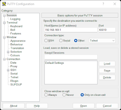
To verify the WiFi adaptor was operating, a computer with a suitably configured WiFi IP address was tested with Putty.

Putty Communications Settings for EPEVER Testing

With the Tera Term debug connection to the WiFi adaptor active, a connection using Putty was established. The packet highlighted in the capture below was received by the WiFi adaptor and appeared consistent with a connection from Putty.

[I/WLAN.mgnt] sta associated mac:bc:09:1b:eb:06:3b
I got a connection from (192.168.169.2 , 51147)
COM<-- FF FB 1F FF FB 20 FF FB 18 FF FB 27 FF FD 01 FF FB 03 FF FD 03


Final Thoughts
The test mentioned in this blog using Putty confirmed that the EPEVER WiFi adaptor worked. A separate test with an Android phone (point-to-point), not mentioned in this blog, did not show the same behaviour.

The access point connection with point-to-point or cloud is not a preferred solution. The WiFi adaptor firmware could likely be reconfigured to operate in station mode. Whether EPEVER is required to rebuild the source, or this option is already provided in the CLI remains to be determined. Station mode is supported by RT-Thread as indicated in the capture below.


[*] Using Wi-Fi framework                /* Using Wi-Fi framework */
(wlan0) The WiFi device name for station /* The default name for station */
(wlan1) The WiFi device name for ap      /* The default name for ap */
(lwip) Default transport protocol        /* Default protocol */
(10000) Set scan timeout time(ms)        /* Scan timeout time */
(10000) Set connect timeout time(ms)     /* Connect timeout time */
(32)  SSID name maximum length           /* Maximum length of SSID name */
(32)  Maximum password length            /* Maximum length of password */
[*]   Automatic sorting of scan results  /* Automatic sorting of scan results */
(3)   Maximum number of WiFi information automatically saved /* Maximum number of WiFi information automatically saved */
(wlan_job) WiFi work queue thread name   /* WiFi work queue thread name */
(2048) wifi work queue thread size       /* wifi work queue thread size */
(22)  WiFi work queue thread priority    /* WiFi work queue thread priority */
(2)   Maximum number of driver events    /* Maximum number of driver events in dev layer */
[ ]   Forced use of PBUF transmission    /* Forced use of PBUF transmission */
[ ]   Enable WLAN Debugging Options      /* Enable WLAN Debugging Options */