Showing posts with label board. Show all posts

Wednesday, 31 May 2023

Circuit Board Return Path Via Placement Options

Introduction
This blog discusses a few options that new circuit board designers may use for return path vias as a result of signal traces changing circuit board layers through using vias.
 
Further Literature

It is highly recommended that existing content from industry figures such as Eric Bogatin or Rick Hartley are reviewed. Related circuit board information is available from YouTuber channels such as Robert Feranec or Phils Lab to mention a few.

PCB Routing Example
For circuit board designs that feature microcontrollers, microprocessors, FPGA or similar devices with high pin count or spacing density the existing connections to power rails through vias can serve as return paths. In the image below, taken from the Altium Mini-PC board, the green highlighted vias indicate the several 0V (GND) power connections that may function as return paths for the DDR memory address, data, clock and control signals.
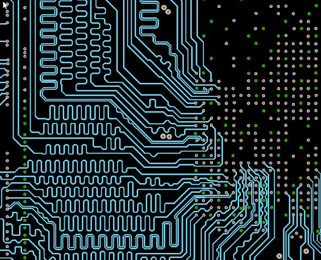
Altium Mini-PC Board Highlighted GND (0V) Vias (Courtesy Altium)
 
Reducing Return Path Distance
The capture below is a further extract from the Mini-PC demonstration board showing a distance measurement between a return via and a differential DDR clock pair.

A Texas Instruments Application Note, High-Speed Interface Layout Guidelines, 2023 states that the signal to return via distance should be a maximum distance of 5 mm (200 mil) although that value could be considered design dependent. For the Mini-PC demonstration board, the distance between the return via and differential pair is small, some 2.1 mm.

Altium Mini-PC Board Differential Via Pair (Courtesy Altium)

Consider a situation where the return path distances needed to be reduced. On the Mini-PC board, a smaller distance could be achieved following a circuit board review. Traces on the layers could be moved to make room for a via closer to the differential via pair. The capture below shows one possible change with a reduction to 1.4 mm.

Altium Mini-PC Board with Closer Return Path Via (Courtesy Altium)

Board Space Limitations
A more common limitation when adding or altering return path vias could be related to circuit board space. In the example below, the traces in the red colour identify a differential pair. There is no return path via in close proximity. The while highlighted rectangles represent pads on the other side of the circuit board.
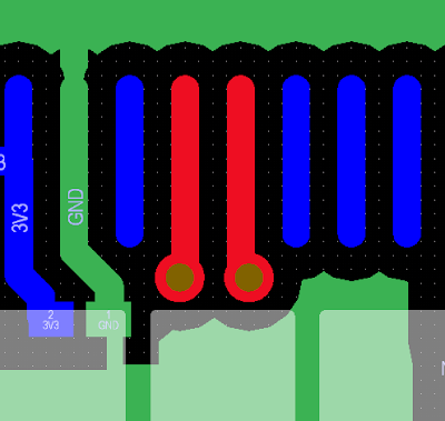
Differential Pair with No Return Path Via on a Double Sided Circuit Board

The reason for no return path via in the area is two-fold. On the opposite side of the circuit board is a surface mount component with large pads making return via placement difficult. The second limitation is due to the PCB rules. The smallest via hole size is configured for 0.3 mm.

The limitation created by the component on the opposite side can be overcome using a number of solutions. Using the existing circuit board via the size of 0.3/0.5 mm (via hole size/via diameter) three vias could be placed onto the circuit board as shown below. This solution yields a differential pair to return path via distance of 2.3 mm.

Differential Pair with Three Return Path Vias on a Double Sided Circuit Board

Differential Pair with Three Return Path Vias on Other Side of Circuit Board

Another solution to consider is changing the board design rules. The circuit board clearance rule could be reduced from 0.2 mm to 0.15 mm since the smaller clearance is supported by many fabrication houses. 

Paired with the board clearance change, the via hole size could be reduced. For instance, a via of hole size and diameter 0.254/0.444 mm could be selected. In regards to capabilities, circuit board fabrication houses can manufacture smaller via hole/diameter measurement of 0.15/0.28 mm (drilled). Applying the two changes mentioned in this section, a via can then be placed less than 1 mm from the differential pair.

Differential Pair with Single Smaller Return Path Via on a Double Sided Circuit Board

No Space or Other Limitations
For some board designs, it may be impractical to place a via close to a signal that requires a return path. Should board space and routing permit, via stitching throughout the board or a via shielding around the board or relevant section of the circuit may be alternative solutions.

Example of Via Stitching on a Circuit Board

Example of Via Shielding on a Circuit Board

Summary
Even though the placement of return path vias may be a semi-automated process with some software design tools, the lack of circuit board space to position vias in optimum locations still vexes novice and experienced board designers alike. This blog puts that other solutions may be found by reviewing the nominated fabrication house’s manufacturing capabilities and the minimum manufacturing circuit board requirements.

Sunday, 30 April 2023

Salvaging from LG Controller Board EBR369328

Introduction
This microblog reviews the electronic components (parts) that could be salvaged from an LG air conditioner compressor inverter controller board.


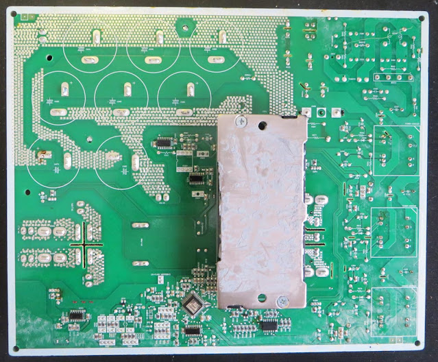
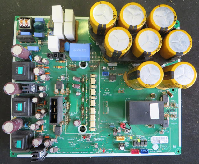
LG Control Board EBR369328 Top Side

Summary
After being provided with the inverter controller board for spare parts, it seems relevant to detail salvageable electronic components in this blog.

Being unfamiliar with air conditioning (AC) equipment, AliExpress was used to identify the function which is listed as an LG three-phase inverter compressor (motor) control board.

It should be noted that the LG control board was supplied not working. In these instances when salvaging electronic parts, additional
testing and diligence should be taken.

Salvageable Top Side Components
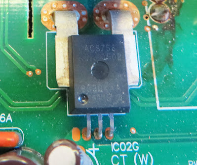
For the current measurement on the three-phase supply, an Allegro device capable of + 50 A, part number ACS756 was utilised. The Allegro part is listed as obsolete however this does not prevent is being used again for testing a
design concept. This is one of the devices that should be tested once removed because of its use in the circuit.

Allegro ACS756
Allegro ACS756

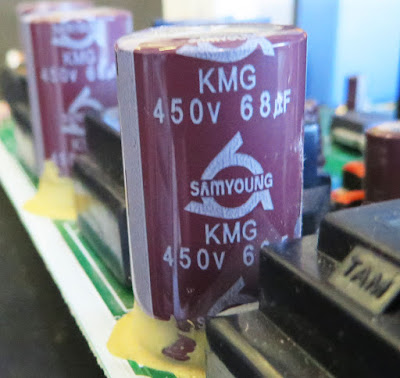
The bulk of the electrolytic capacitors are manufactured by the Korean company, Samyoung. Some of the electrolytic through-hole capacitors associated with the mains (line) supply may be handy for spares if mains voltage projects are an area of interest.

Mains Rated Electrolytic Capacitor

The large 10 to 20 W wire-wound ceramic resistors had no signs of overheating or physical damage. These resistors may be worth salvaging even for simple dummy loads.

Wirewound Resistors
Wirewound Resistors

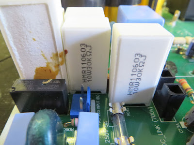
Located near the wire-wound resistors are mains capacitors manufactured by the Korean company, Pilkor. On this LG board, those capacitors were in excellent condition and worth salvaging.

Mains Capacitors
Mains Capacitors

The large vertical connector, AMP series D-5200, should be considered for anyone involved with high-current designs.

AMP Connector D-5200

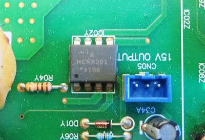
The circuit board is fitted are a few different types of optocouplers. One of the interesting parts is the HCNR201 which is a high-linearity optocoupler from Broadcom.

Broadcom HCNR201
Broadcom HCNR201

Other optocouplers include Toshiba TLP781, TLP559 and TLP521. All these Toshiba optocouplers are obsolete however they may serve well as spares or for repair purposes.

Various Toshiba Optocouplers

A TE relay with the part number T92S7D12-12 is fitted to the board. This relay is rated at a 12 V at 20 A and is still actively manufactured by TE.

High Current TE Relay

Contained on the board are a plethora of remaining components to consider for salvage. These include an oscillator, heatsinks, LEDs, chokes, axial resistors and unidentified components.

Salvageable Bottom Side Components
Fitted on the bottom side of the PCB is the motor switching module (IGBT). This device is most likely not worth salvaging.

Motor Driver Module
Motor Driver Module

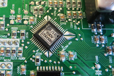
The semiconductors on the bottom side appear to have no identification markings or those markings have become obscured by what appears to be a protective (conformal or lacquer) coating.

LG Control Board EBR369328 Bottom Side

All electronic parts on the bottom side of the board are epoxy glued to the as part of the circuit board assembly process. There is little to salvage from this side of the board because of the glue although removing components is possible with the correct tools. For low-cost and high-throughput printed circuit board assemblies, soldering using wave solder in a single pass has been a common manufacturing method. This LG board employs some solder-thieving designs in the circuit board layout as pictured below.

Component with Solder Thieving Pads

Saturday, 19 November 2022

EPEVER MPPT to Elfin EW11A Adaptor Circuit Board

Introduction
This blog follows on from a previous post relating to WiFi communication with an EPEVER MPPT. In this post, a DIN rail mount adaptor was created to power the Elfin EW11A (WiFi to RS485) device.

EPEVER MPPT to Elfin EW11A Adaptor

Wiring
In a previous post, the connection to an EPEVER MPPT was tested using an Elfin EW11A that was set up for station-mode WiFi operation. The test wiring described in this post was clumsy so a permanent fixture was designed.

DIN Rail Mount Solution
The connections required for the circuit board between the MPPT and EW11A were already established and tested. To power EW11A, a Texas Instruments DC-DC buck converter was selected. 

To mount the circuit board containing the aforementioned parts and rather than spinning up a 3D printed part, Adafruit’s DIN rail mount was used.

Schematic
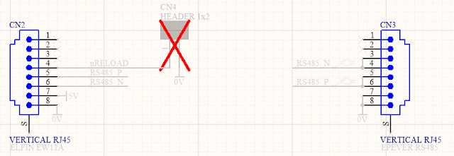
The RS485 schematic connection between the MPPT and EW11A using RJ45 connectors is shown below.

Circuit Board Connections for EPEVER MPPT to Elfin EW11A

In the power supply circuit shown below, a reverse polarity protection diode is at the front end of the design. Following the polarity diode is an optional transient diode (TVS) clamp and PI filter. Bypassing the filter is possible using the two optional bypass resistors which were added in revision 1 of the circuit board. Powering the EW11A is a DC-DC buck converter, notably the Texas Instruments LMR14203; no linear regulators here. At the time of writing the lead time of TI regulators exceeds a year so some equivalents could be the LMR16006X, LMR16006Y or MP2451DJ; these alternatives should be reviewed for compatibility.

Circuit Board Connections for Elfin EW11A Power Supply

For the sundry items on the board, a power LED was included but to conserve power this device could be unpopulated or the series current limiting resistor increased.
To reset the EW11A, a pair of circuit board pins were provided on the circuit board. Shorting the two pins provided on the circuit board will perform the reset.

Circuit Board (PCB)
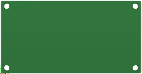
The board shape was designed using the dimensions shown on the DIN holder datasheet (Adafruit website). The fitment of the circuit board in the DIN holder was accurate, although the placement of components near the edge of the circuit board was tight. A larger keep-out for the components from the edge of the circuit boards was included in the next revision of the board.

EPEVER MPPT to Elfin EW11A Circuit Rev 1 Board Top Layer

EPEVER MPPT to Elfin EW11A Circuit Board Rev 1 Bottom Layer

Testing
The populated circuit board was powered with DC 24 V and load-tested. No temperature, climate or similar tests were performed.

With no load, the DC output voltage was 5.02 V with a quiescent current of 5 mA (LED). The output voltage dropped to 4.98 V when the EW11A was powered by the regulator. Greater than DC 6 V should be provided to the DC-DC converter for stable operation.

EPEVER MPPT to Elfin EW11A Circuit Board Rev 0 Bottom Layer

A functional soak test of the circuit board over a 24-hours showed no issues. No dropped packets were detected by the virtual COM port application "HW Virtual Serial Port", version 3.1.2.

Downloads
Listed below are the MPPT to EW11A adaptor schematics, circuit board Gerber files and project Bill of Materials. The blank circuit boards can be made available at PCB Way using their Shared Projects option. The supplied schematic and Bill of Materials are for a fully populated circuit board.

Disclaimer: Please note that revision 0 of the the circuit board was tested in this post; no functional changes relating to the MPPT or EW11A connections were made in revision 1 of the circuit board.

Elfin to EPEVER Rev 1 Schematic

Elfin to EPEVER Rev 1 PCB

Elfin to EPEVER Rev 1 BOM (Full)
Elfin to EPEVER Rev 1 BOM (Full) Excel

Elfin to EPEVER Rev 1 Gerber and NC Drill

Sunday, 20 February 2022

Example Lids as Circuit Boards (PCB) Part 2

Summary
This short blog
follows on from the previous blog listing some drawings for lids/plates that were replaced with circuit boards.

Hammond 1455N1601 with Press Fit Panel

Circuit Boards Lids
While the previous blog used a clearance of at least 0.1 mm per edge, some of the new lids used an interference fit. Board dimensions should be validated to suit each design.

Again for verification, the Altium Designer files were saved as STEP files, converted to STL files then 3D printed before manufactured.

The DXF files below were generated using the Export feature in Altium Designer. The listed DXF files can be imported into an Altium PCB project using measurements in millimetres.

PCB Lid DXF for NUB505017

Tuesday, 30 November 2021

Example Lids as Circuit Boards (PCB)

Summary
This short blog
lists a handful of drawings for lids/plates of instrument cases that were replaced with circuit boards.

Example Project using 3D Printed PCB Panel (Multicomp MC002212)

Front Plates as Circuit Boards
The lid or plate on an instrument case is commonly manufactured as a plastic such as ABS, diecast aluminium or steel. These can be readily be replaced with a circuit board. Some of the benefits and drawbacks of using the circuit board are listed below.

  1. Customised appearance and colour in a single process (no separate decal or printing),
  2. Electronics can be added to the circuit board providing additional real estate,
  3. Circuit board may have benefits for EMC compared to standard plastic items (not metal screened),
  4. Minimal to no machining or manufacturing work for the circuit board,
  5. Iterating circuit board designs may end up faster than updating CAD for metal lids or plates,
  6. Plastic or metal lid or plate becomes waste or at best recycled if not used,
  7. Reworking a circuit board for mechanical purposes is not always possible,
  8. Circuit boards usually require more processes to recycle.

Example Lids as Circuit Boards
Shown below is a generic plastic enclosure called a jiffy box with a 3D plastic lids designed in Altium. 

A clearance of at least 0.1 mm per edge was chosen however the clearance should be adjusted as required due to variations in manufacturing.

Jiffy Box with 3D Printed PCB Plate

 
For verification, the Altium Designer files were saved as STEP files, converted to STL files then 3D printed. The files below were generated as DXF files using the Export feature in Altium designer. These DXF files can be imported into an Altium PCB, using a measurement in millimeters with the board shape defined on Mechanical-1.

PCB Lid DXF for Jiffy Box UB3


PCB Lid for Hammond (Eddystone) 27969PS


PCB Lid for Multicomp (Element14) MC002212


Friday, 25 September 2020

Altium PCB Art

Summary
This blog outlines techniques 
to produce PCB visual art utilising a Printed Circuit Board (PCB) design package with image editing software. Below is an example of a PCB, with exposed copper, portraying a Monkeyface.

Monkeyface as PCB Artwork

Preamble
During the pandemic lockdown, there was an opportunity to use a PCB design package, Altium Designer (Altium), for basic visual 'PCB' art. While Altium can be used independently to create visual art, utilising a free image editing package such as GIMP, Inkscape or a commercial package such as Photoshop or Corel will assist with altering images.

The image editing methods described in this blog are experimental; alternative techniques are welcomed!

Software Alternatives
Free PCB software design packages which include KiCad, Design Spark and PCBWeb are capable of creating similar PCB art.

Source Material
Source material, such as an image or a DXF file, are usually required with a PCB design package. Monochrome images can ordinarily be pasted directly into Altium however loss in greyscale images can occur with lighter tones. Colour images require conversion to black and white. Images can be converted into a DXF format and imported into Altium.

Example 1: Colour to Monochrome - Cloud Sun
All credit to the creator of the artwork
Sushant Wadte, for the example image below.

Colour images are changed into monochrome using various methods. The subsequent method, using filters in Inkscape, produces reasonable results in images with large objects.

Cartoon Sun Cloud
Cartoon Sun Cloud - Courtesy PNGItem. Creator - Sushant Wadte

Using the 'Greyscale' filter in Inkscape, the colour image was converted to monochrome. The colour channels and lightness were adjusted to improve the monochrome image.

Inkscape Greyscale Filter - Cartoon Sun Cloud

For importing into Altium, the monochrome image background was changed to white and all other features were converted to black.

Inkscape Black and White Cartoon Sun Cloud

Filling the cloud and sun rays with black was performed using Inkscape's fill bounded areas tool. The image background was filled with white.

The converted image was saved as a BMP and PNG file.

Altium Script (Alternative Import Method)
The Altium script PCBLogoCreator was used to convert the bitmap image into a representation in tracks.

Inkscape Dialog Box Running PCBLogoCreator Script
Altium Dialog Box Running PCBLogoCreator Script

Running the Altium script on the black and white image for a PCB, yielded the resulting image shown below.

Altium Script Converted Cartoon Sun Cloud
Altium Script Converted Cartoon Sun Cloud 

The image converted by the script was useable, although there are two points to highlight. 
Firstly, converting the image results in hundreds of tracks which can load up the CPU when moving the tracks. Secondly, the tracks cannot be selected and converted to a polygon or region.

Altium Script Conversion Lines Cartoon Sun Cloud

Placing Sun Cloud PNG Into Altium
The saved PNG image can make its way into Altium using two methods. One method is to cut and paste into an Altium PCB. Another method is to use the menu command, Place Object.

The same black and white image in the previous section was pasted into Altium onto the top layer (copper).


Altium Pasted PNG Cartoon Sun Cloud

Selecting the cloud on the pasted image shows that the process of pasting into Altium converts the image dark areas to regions.

Object Tweaks
The image was initially pasted on the PCB top layer (copper) although it is possible to paste onto other layers such as the top overlay (silkscreen).

Altium 3D Top Silk Unmodified Cartoon Sun Cloud

The cloud was changed to top layer silk and the sun and rays left as copper. To change the cloud from top copper to top silk, the cloud region was modified.

Altium Cloud Region Selection

The Properties (legacy PCB Inspector) was opened to change the region from top copper to top silk. 

Altium Region Layer Change

With the cloud changed to silk, the remaining objects required removal of the solder mask (green coating).

Altium Top Silk Cloud Region
Altium Top Silk Cloud Region 

To alter the solder mask of the remaining objects, each region was selected. The region 'Properties' (legacy PCB Inspector) was opened and the 'Solder Mask' rule changed.

Altium Object Solder Mask Expansion
Altium Object Solder Mask Expansion

The 'Solder Mask Expansion' setting was set to 'Manual'. Having a 'Solder Mask Expansion' value may be required depending on the capabilities of the PCB manufacturing house.

The resulting capture of the PCB, in 3D, shows the changes.

Altium 3D Modified Cartoon Sun Cloud

PCB Shape - Cloud Sun
The PCB outline was defined using tracks on Mechanical 1 layer as this layer is commonly used to define the shape of the PCB.

PCB Finish - Cloud Sun
For the example PCB displayed above, a green solder mask and ENIG copper finish (gold) were used. Some alternative solder mask colours are red, blue, yellow, white, black and purple. The copper can be left raw to discolour due to oxidisation or coated with a finish such as lead-free solder, tin, silver or gold.


Example 2: Colour to Monochrome - Monkey
Converting the monkey image for use as art in Altium used a similar method to the first example.

Monkey Face - Courtesy free.clipArtOf.com
Monkey Face - Courtesy Free.ClipArtof.com

Some additional work was required to remove the colour and gradients. Firstly, the Greyscale filter in Inkscape was used to convert the image to monochrome.


Inkscape Greyscale Filter - Cartoon Monkey Face

Using the 'Fill Bounded Areas' tool in Inkscape, the areas with colour gradients were filled with white. There was a gradient (shadow) below the face which was also filled with white. 

Inkscape Monkey Face Monochrome No Shading

Visible lines in the image may be imported by Altium and therefore these lines were removed. Using Inkscape's 'Brilliance' filter, the Brightness and Lightness settings were adjusted to remove the lines. Producing the desired results with this tool can take some tweaking.

Inkscape Brilliance Filter - Cartoon Monkey Face

Monkey Black and White
The cut and paste results in Altium are significantly improved when all colours are black. The 'Fill Bounded Areas' tool was used to ensure all regions were converted to black.

Inkscape Cartoon Monkey Face All Black Lines

The image in Inkscape was exported as a PNG ready for import into Altium.

Placing Cartoon Monkey PNG Into Altium
Using the Place Object command in Altium, the Cartoon Monkey was added to a new blank PCB on the top copper layer.


Altium Cartoon Monkey Face Import

Object Tweaks
For the Monkey design, all copper areas were changed to show exposed copper. The Solder Mask expansion changed to manual for all the copper areas.

Altium Cartoon Monkey Face Copper Selected

Viewing in 3D showed that the solder mask was removed from the copper.

Altium Cartoon Monkey Face Exposed Copper

PCB Shape - Monkey
The PCB outline was defined using arcs around the Monkey head. These arcs were drawn on the Mechanical 1 layer as shown in the image below.

Altium Cartoon Monkey Face Mech1 Layer

Setting the PCB shape was performed with the Mechanical 1 Layer arcs selected then using the Altium command Define PCB from Selected Objects.

Altium Cartoon Monkey Face Board Cutout

Final Touches - Monkey
Holes were made for the Monkey eyes using two pads having a 3.8 mm holes.

Altium Cartoon Monkey Face Eye Holes

Pictured below is the final PCB in 3D with exposed copper and holes for the eyes.

Altium Cartoon Monkey Face Final

PCB Finish - Monkey
A black solder mask and ENIG copper finish (gold) were used for the PCB finish.

Example 2: Alternative Monkey
To achieve a PCB design similar to the image shown at the beginning of the blog, the black and white image required inversion. At the previous step 'Monkey Black and White', the image was inverted.

Monkey Head as PCB Artwork

The Inversion Filter in Inkscape performed the conversion.

Inkscape Invert Cartoon Monkey Face

Adding a Border
After the Inversion, the image boundaries became the four extremities of the Monkeyface. Adding a black background using Inkscape assisted when importing the image into Altium.

Inkscape Monkey Face Inverted with Border

With a black rectangle drawn in Inkscape, the inside area was filled with black. 

Inkscape Monkey Face Inverted with Background

Placing Cartoon Monkey PNG Into Altium
Below is the PCB capture after using the Place Object command in Altium.

Altium Cartoon Monkey Face Alternate Import

Object Tweaks
For the alternate Monkey design, the internal copper areas were changed to exposed copper.

Altium Cartoon Monkey Face Alternate Exposed Copper

PCB Shape - Monkey
The PCB outline comprised of two parts, a board cutout and the PCB shape on the Mechanical 1 layer. Firstly, the remaining copper region outside the Monkeyface was selected then changed into a 'Board Cutout'.


Altium Copper Region to Board Cutout

Viewing in 2D shows the board cutout.

Altium Cartoon Monkey Face 2D Cutout

Secondly, a Mechanical 1 Layer was added onto the PCB to define the physical PCB size. The Mechanical 1 Layer tracks were selected and the PCB shape was defined from the selected objects.

Altium Cartoon Monkey Face Alternate Mech 1 Layer

Viewing the PCB in Altium 3D.

Altium Cartoon Monkey Face Alternate Final

Alternative PCB Shapes
Inkscape provides a tool called Trace Outline which can be useful when the shape of the PCB must be marginally different to the image shape. A modified outline can be imported into Altium as a separate object which would then be used to define the outline of the PCB.

Inkscape Monkey Face Trace Outline

Final Thoughts
The methods described in this blog can be used independently or partnered with electronic circuits to create visual PCB art. 

It should be noted that the placement of copper as art is not limited to either side of the PCB but internal copper layers also. Using only internal copper and a thinner PCB (1 mm or less) produces near translucent effects with the suitable backlighting.