Introduction
This blog details a prototype flasher circuit board for a school Maker community. The board design is built to accommodate through-hole and surface mount components. Featuring two component mounting styles allows the board to serve multiple uses in a school environment.
 |
| Dual LED Flasher PCB |
Circuit
The circuit in the blog uses a well-worn astable LED flasher design made with discrete components. A transistor pair, wired in a common emitter configuration that drives a total of four LEDs were used. As a DC 9 V battery powers the circuit, more LEDs could be added to the design to interest young Makers.
PCB
An ABS enclosure from a local supplier was initially chosen for the prototype. PCB dimensions and the mounting hole locations for the circuit board were extracted from the ABS enclosure.
Components for the flasher circuits were placed on the top layer of the board. The battery connector was relegated to the bottom layer allowing a battery to be placed inside the ABS enclosure. Routing of the board used two copper layers.
 |
| Dual LED Flasher Routed PCB |
3D Printed Case
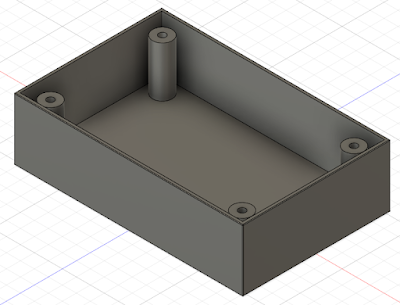
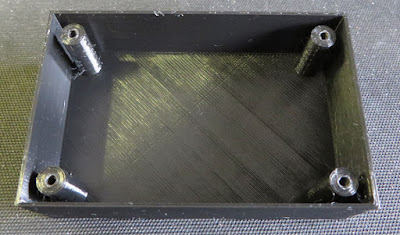
With many Makers communities having 3D printers a printed enclosure was created based on the commercially available product
 | |
| 3D Model of Plastic Case |
The Fusion 360 and STL files are located at the end of this post.
 |
| 3D Printed Plastic Case |
Making
The image below shows the through-hole portion of the circuit board
after being populated and partly soldered by a school student.
 |
| Half Populated LED Flasher Board |
All the
through-hole LEDs and capacitors were taken from salvaged components.
To hold the circuit board in position, round head metal self-tapping screws, 3 mm between crests, 7.5 mm in length were utilised.
The surface mount portion of the board was hand populated as a second step for this blog as can be seen in the image below.
 |
| Fully Loaded Flasher PCB in 3D Printed Plastic Case |
The video below shows the through hole portion of the flasher board operating.
The second image shows the surface mount section in operation during testing.
Captures from Circuit
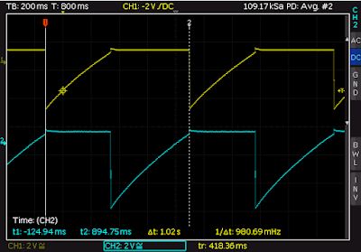
For those Maker communities interested in checking the circuit waveforms with a oscilloscope, below are some captures taken from the transistor collector and base connections.
 |
| Voltage Measured at Transistor Collector |
 |
| Voltage Measured at Transistor Base |
Summary
The LED flasher detailed in this blog was published as an example for Maker communities. Available for download below is the artwork for the circuit board and the file for a suitable 3D-printed case.
 | |||||
| Flasher Schematic |
 |
| Flasher PCB |
 |
| Flasher Gerber |
 |
| Flasher PCB Bill of Materials |
 | ||
| 3D Case in Fusion 360 |
 |
| 3D Case as STL* |
* If the plastic case is used, 4 x round head metal self-tapping
screws, 3 mm between crests, 7.5 mm long may be required.


No comments:
Post a Comment