Introduction
This blog continues from a prior post, Voltage Interruption Tester for IEC 61496-1 Part 5. The interruption tester code detailed in that post was updated to suit supply dips or interruptions specifically to meet the standard EN 61000-4-29.
This original project was posted as a novel example of testing for changes in voltage. However, as interest in this project has been increasing specifically for the DC tests listed in the standard EN 61000-4-29, the code was changed to perform these tests only.
Code Changes
Code changes were implemented in the interruption tester for a closer approximation of EN 61000-4-29 and to improve the code portability between Infineon (Cypress) processors. In the EN 61000-4-29 standard, five tests are listed for DC voltage dips with fixed times of 10 ms to 1 s. An extract from the standard is shown below.
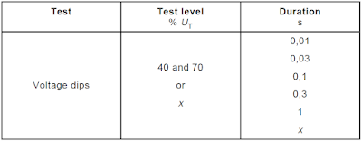 |
| DC Voltage Dip Table from EN 61000-4-29 |
The PWM functionality in the Infineon microcontrollers, configured through the PWM component, was disabled.
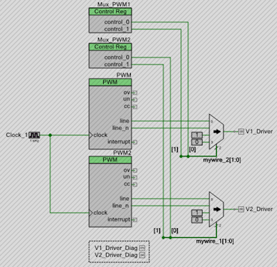 |
| Interrupt Tester Project Disabled PWM Logic |
For the reduction in resources controlling the output pins between Cypress PWM and software output control, the Universal Digital Blocks (UDBs) dropped by almost 50 %.
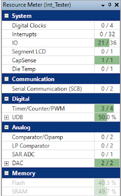 |
| Previous Project PSoC Resource Usage |
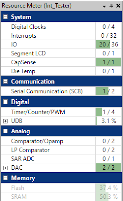 |
| Updated Project PSoC Resource Usage |
The
system timer was used as the replacement for the PWM component. Output pins
that were PWM controlled are controlled directly in code. To improve the
output waveform timing accuracy, the system timer was reconfigured from
10 ms to 1 ms.
Testing Code Changes
Timing control of the outputs controlling the load was performed in the corresponding function listed below.
/** *****************************************************************************
* Function Name: Output_Handler
*
* @brief Run interruption tests with timing below, 10 s separation between tests
*   Test 1 - 10 ms
*   Test 2 - 30 ms
*   Test 3 - 100 ms
*   Test 4 - 300 ms
*   Test 5 - 1000 ms
*
* @return none
****************************************************************************** */
void Output_Handler(uint8_t output_CurMenuItem, uint8_t out_statemachine)
{
    static uint8_t output_savedMenuItem;
    static uint8_t output_driver_state;

    if ((out_statemachine == OUTPUT_ON) && (output_CurMenuItem != 0))
    {
        /* Handle PWM 1 Settings */
        if ((output_driver_state == OUT_OFF) || ((output_driver_state == OUT_LOW) && ( Pulse_Low_Ctr == 0)))
        {
            Pulse_High_Ctr = PWMValues[output_CurMenuItem].COMPARE1;
            Pulse_Low_Ctr = 0;
            output_driver_state = OUT_HIGH;
            V1_Driver_Write(true);
            V2_Driver_Write(true);
        }
        else if ((output_driver_state == OUT_HIGH) && ( Pulse_High_Ctr == 0))
        {
            Pulse_Low_Ctr = PWMValues[output_CurMenuItem].PERIOD1;
            output_driver_state = OUT_LOW;
            V1_Driver_Write(false);
        }
        output_savedMenuItem = output_CurMenuItem;
    }
    else if (out_statemachine != OUTPUT_ON)
    {
        V1_Driver_Write(false);
        V2_Driver_Write(false);
        output_driver_state = OUT_OFF;
    }
}
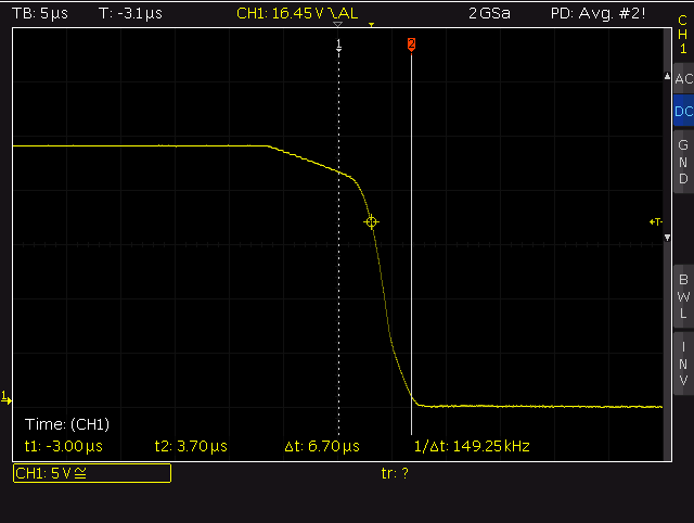
The standard EN 61000-4-29 standard states requirements for the rise and fall times when the tester is driving a 100 R load (1 us to 50 us).
 |
| Test Generator Requirements from EN 61000-4-29 |
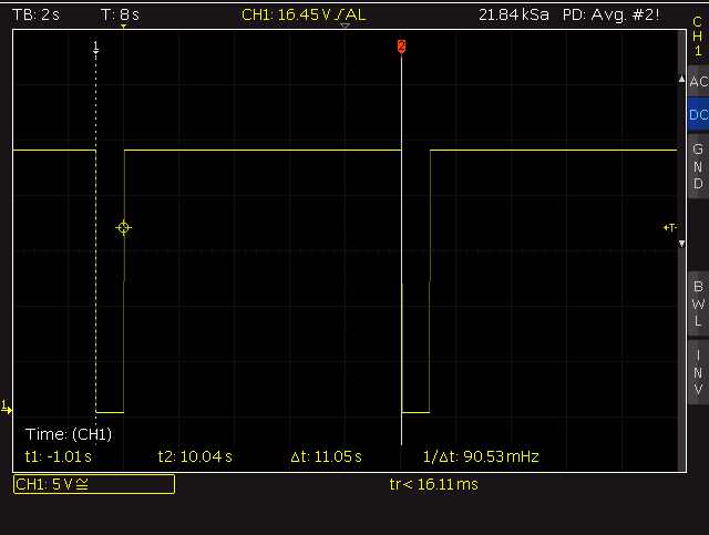
The pulse duration and time between tests were validated with the load.
 |
| 10 ms Interruption Tester Output |
 |
| 100 ms Interruption Tester Output |
Testing showed that measured rise times were less than 18 us and the fall time less than 7 us.
 |
| Rise Time 10-90 % with 100 R Load |
 |
| Fall Time 10-90 % with 100 R Load |
Future Changes
To facilitate other microcontrollers, another revision of the display circuit board without capacitive sensing, a flat flex inter-board connection, watchdog and adding a third channel to the power board will be investigated.
Downloads
Listed below is the PSoC Creator project.
 |
| Interruption Tester 0.1c PSoC Project |

No comments:
Post a Comment