Showing posts with label enclosure. Show all posts

Sunday, 20 February 2022

Example Lids as Circuit Boards (PCB) Part 2

Summary
This short blog
follows on from the previous blog listing some drawings for lids/plates that were replaced with circuit boards.

Hammond 1455N1601 with Press Fit Panel

Circuit Boards Lids
While the previous blog used a clearance of at least 0.1 mm per edge, some of the new lids used an interference fit. Board dimensions should be validated to suit each design.

Again for verification, the Altium Designer files were saved as STEP files, converted to STL files then 3D printed before manufactured.

The DXF files below were generated using the Export feature in Altium Designer. The listed DXF files can be imported into an Altium PCB project using measurements in millimetres.

PCB Lid DXF for NUB505017

Tuesday, 30 November 2021

Example Lids as Circuit Boards (PCB)

Summary
This short blog
lists a handful of drawings for lids/plates of instrument cases that were replaced with circuit boards.

Example Project using 3D Printed PCB Panel (Multicomp MC002212)

Front Plates as Circuit Boards
The lid or plate on an instrument case is commonly manufactured as a plastic such as ABS, diecast aluminium or steel. These can be readily be replaced with a circuit board. Some of the benefits and drawbacks of using the circuit board are listed below.

  1. Customised appearance and colour in a single process (no separate decal or printing),
  2. Electronics can be added to the circuit board providing additional real estate,
  3. Circuit board may have benefits for EMC compared to standard plastic items (not metal screened),
  4. Minimal to no machining or manufacturing work for the circuit board,
  5. Iterating circuit board designs may end up faster than updating CAD for metal lids or plates,
  6. Plastic or metal lid or plate becomes waste or at best recycled if not used,
  7. Reworking a circuit board for mechanical purposes is not always possible,
  8. Circuit boards usually require more processes to recycle.

Example Lids as Circuit Boards
Shown below is a generic plastic enclosure called a jiffy box with a 3D plastic lids designed in Altium. 

A clearance of at least 0.1 mm per edge was chosen however the clearance should be adjusted as required due to variations in manufacturing.

Jiffy Box with 3D Printed PCB Plate

 
For verification, the Altium Designer files were saved as STEP files, converted to STL files then 3D printed. The files below were generated as DXF files using the Export feature in Altium designer. These DXF files can be imported into an Altium PCB, using a measurement in millimeters with the board shape defined on Mechanical-1.

PCB Lid DXF for Jiffy Box UB3


PCB Lid for Hammond (Eddystone) 27969PS


PCB Lid for Multicomp (Element14) MC002212


Saturday, 1 December 2018

Isolation Transformer Build Medical Grade 240V

Summary
This blog details the build process of an enclosure for isolation transformer using a medical grade toroidal transformer.

Medical Grade Transformer
There are significant benefits in using a medical grade toroidal transformer over a standard type. These include multiple layers of winding insulation, reduced leakage currents and certain types of internal transformer failures can lead to a winding short to mains earth resulting in protected equipment and operators. Such a short to mains earth is achieved because a medical transformer contains a dedicated mains earth connection. Medical transformers are usually made to a international standard such as IEC / UL 60601-1.

Transformer Selection
A transformer manufactured by Triad Magnetics (China) was selected for mains 240VAC. The Triad Magnetics parts VPM240-670 is rated at 160VA which is usually ample for fault finding equipment or powering small pieces of test equipment. 


Triad Magnetics VPM240-670
The transformer features a number of winding options for 110VAC or 240VAC.

Triad Magnetics VPM240-670 Side View
For this design the primary and secondary will be configured for 240VAC operation.

Hardware Selection
In addition to the transformer are a number of key components such as the enclosure, IEC connectors, fuses and switch. A standard plastic enclosure was chosen to house the transformer as the expected operational time was low. For long operating periods a vented case would be used.


Enclosure
Enclosure
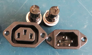
Shown below are the fuse holders and IEC inlet outlet chassis mount connectors.


Associated Isolation Transformer Hardware
Hardware Mounting
The hardware required for the design was measured and the mark-ups were made on opposite ends of the enclosure.


Inlet and Fuse holder Mounting
Outlet and Fuse holder Mounting
Standalone 3AG fuse holders were chosen over IEC connectors with integrated M205 type fuses however either is suitable for this design.


Transformer Mounting
Mounting for a double pole rocker switch and the transformer were added.

Hardware Dry Fit
Each piece of hardware was mounted to ensure that fitting was suitable and clearances were sufficient.


Hardware Dry Run
Hardware Dry Run
Enclosure Wiring
Salvaged mains 300V AC rated cable was used to wire between the IEC connectors and the fuses.


300V Mains Cables
300V Mains Cables
All mains connections were soldered and the mains wire was passed through the eyelet as shown below.


IEC Mains Cable Connection
All connections were insulated with heat shrink tube.


Fuse with Heatshrink
Fuse with Heat shrink
 
The image below shows the rather snug wiring prior to testing. Additionally, while tightening the IEC fixings the case cracked meaning the entire case would need to be replaced after some initial testing.


Wired Isolation Transformer
Regulation Testing
The transformer was wired for 240V AC on the primary and secondary.


Transformer Input and Output Options
 
Shown in the image below are the transformer windings as detailed on the Triad Magnetics datasheet.

Transformer Windings
Using the wiring configuration for 240VAC, regulation measurements were performed to approximately 130VA using a Fluke 325.


Triad Magnetics Transformer Regulation
 
With a load of 130VA the transformer regulation was approaching the 7.2% maximum quoted regulation of the transformer at full load.

Comments 
With very small loads the transformer secondary voltage is almost 10% higher than the primary voltage. For voltage sensitive equipment this differential may be a limiting factor although for standard bench testing this transformer is more than suitable.