Summary
This blog provides details of a novel voltage interruption tester that
demonstrates the requirements listed in the
IEC 61496-1 standard, section 4.3.2.2.
The tester was needed because certain types of electronic hardware must
be tested to the IEC 61496-1 standard and dedicated testing facilities
have had reduced access during the pandemic. The purpose of the
tester in this blog is preliminary testing which would not replace an
authorised testing facility.
Description
The interruption test hardware described in this blog was
designed for DC systems to 48 V and currents to 3 A. For design
constraints, interruption timing was considered important,
followed by access to available hardware then output voltage
regulation.
The capture below displays section 4.3.2.2
of the IEC standard which shows the timing of the three
interruption tests.

|
| Supply Voltage Interruptions |
Hardware Solutions
Off the shelf power supply evaluation boards such as the Vishay SiC461 were tested initially. To control the output voltage, a programmable resistor replaced one of the feedback elements. By using a programmable resistor, a 10 ms pulse width was achievable. However, the output voltage rise and fall times were asymmetrical and several milliseconds in duration.
Alternative solutions utilising linear regulators such as the LM317T were analysed. The linear regulator produced very sharp output voltage rise and fall times. The limitation of the linear regulator was the LM317 voltage regulation and accompanying device heat dissipation.
By utilising existing resources, such as individual benchtop supplies, a simpler solution was identified. It was likely that workspaces would have access to one dual output or two single regulated adjustable power supplies. These supplies could be used together for the switching tests.
The hardware in the system consisted of a microcontroller (PSoC) that interfaced to a pair of optocouplers (4N28) in turn driving two high-side switches (BTS50085). The output of each high-side switch was tied together with series diodes (1N5404) to produce the output.
One design weakness using this solution was the supply to output voltage drop. As the cumulative voltage drop of the high-side switch and diode changed with load current, the power supplies required adjustment to achieve the correct test voltages.
Hardware Concept
Shown below was the original concept
proof of the hardware. The high-side
switch datasheet lists an operating
voltage to some 58 V and a current of 11
A.

|
|
Interruption Tester Concept Hardware |
Circuit Overview
Control signals generation was performed by a microcontroller; any type could perform the task as the signals are slow-moving. Two control signals from the microcontroller drive a set of optocouplers. For this design, an ancient pair of 4N28’s were fitted.
The transistor output of the optocouplers switched the high-side driver inputs to 0 V. This was required as the inputs of the high-side drivers BTS50085 must be switched to 0 V to activate their outputs.
Microcontroller
An off the shelf CY8CKIT-059 Cypress development board
implemented a PWM to drive two outputs for the optocouplers.
The onboard switch and LED acted as the user interface.
Repetitive switch presses selected a subsequent test. Flashes from the onboard blue LED indicated the test number. No flash for off, one flash for test one up to three flashes for test three.
For the top design in PSoC Creator, the first PWM output provided the
timing for the voltage dip. The second PWM output configuration and some
flip flops ensured that the half voltage was active before and after the
first PWM changed state. Understandably there are other ways to use the
PWM component, again this was a concept proof.

|
|
PSoC Creator PWM Test Setup |
The PWM was configured as illustrated below. Settings were controlled
from within the code.

|
|
PWM Component Setup |
The rise and fall times (10%, 90%) were 20 us and 90 us
respectively
with the output driving a resistive load.

|
|
Rise Time for Resistive Load |

|
| Fall Time for Resistive Load |
Output
Waveforms
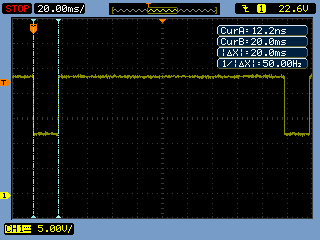
The following captures were taken when driving a resistive
load.

|
| Interruption Test 1 with Resistive Load |

|
|
Interruption Test 2 with Resistive Load |

|
|
Interruption Test 3 with Resistive Load |
The next captures were taken when driving a DC 12 V fan.

|
| Interruption Test 1 with DC Fan |

|
| Interruption Test 2 with DC Fan |

|
| Interruption Test 3 with DC Fan |
Output
Voltages
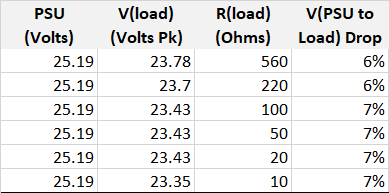
For the three interruption tests, various loads were tested and
peak voltages measured.

|
| Interruption Test 1 with Various Resistive Loads |

|
|
|

|
| Interruption Test 3 with Various Resistive Loads |
The above test results show that adjustment to the power supply voltages was required to accommodate for the system voltage drop.
PSoC
Code
Listed below is the test code for the PSoC controller.
/**
* @file main.c
* @brief Basic example of IEC61496-1 tests
* @version 0
*
* History
* Version       Change Notes
* 0.0           Test code
*/

#include <project.h>
#include <stdbool.h>

/* Prototypes */
void led_flash_state(uint8 state_num);


/**
* @brief Flash LED
* @param state
*/
void led_flash_state(uint8 state_num)
{
    while (state_num != 0)
    {
        LED_Write(true);
        CyDelay(250);
        LED_Write(false);
        CyDelay(250);
        state_num--;
    }
}

/**
* Main
*/
int main()
{
    CyGlobalIntEnable;

    uint8 state = 0;
    uint8 state_update = false;

    for(;;)
    {
    if (SW1_Read()== false)
    {
        CyDelay(200);                    /* Some debounce */
        state++;
        state_update = false;
        if (state == 4)                  /* Toggle states */
        {
            state = 0;
        }
    }

    if ((state == 0) && (state_update == false))
    {
        PWM_Stop();
        state_update = true;            /* No PWM in first state */
    }

    if ((state == 1) && (state_update == false))
    {
        PWM_Stop();                     /* Test 1 - 10 ms 100% dip */
        PWM_WritePeriod(999u);
        PWM_WriteCompare1(110u);        /* Control PWM output 1 */
        PWM_WriteCompare2(0u);
        PWM_WriteControlRegister(PWM_CTRL_ENABLE);
        PWM_Start();
        led_flash_state(state);
        state_update = true;
    }

    if ((state == 2) && (state_update == false))
    {
        PWM_Stop();                      /* Test 2 - 20 ms 50% dip */
        PWM_WritePeriod(1999u);
        PWM_WriteCompare1(200u);
        PWM_WriteCompare2(210u);         /* Control PWM output 2 for lower voltage */
        PWM_Start();
        led_flash_state(state);
        state_update = true;
    }

    if ((state == 3) && (state_update == false))
    {
        PWM_Stop();                      /* Test 3 - 500 ms 50% dip */
        PWM_WritePeriod(49999u);
        PWM_WriteCompare1(5000u);
        PWM_WriteCompare2(5010u);        /* Control PWM output 2 for lower voltage */
        led_flash_state(state);
        state_update = true;
    }
  }
}

/* End */
Summary
For concept proof, the tests using high-side switches controlled by a microcontroller verified specific requirements detailed in the IEC 61496-1 standard. During tests, the input to output voltage drop was less than 10 %. Compensation for voltage drop was achieved by adjusting power supply voltages.
Depending on design requirements, a different microcontroller, high-side switches with a lower operating voltage, or alternative components could be selected. If isolation from the switched output voltage was not a consideration, the optocouplers could be omitted.
With access to testing facilities being limited, having the hardware to provide preliminary on bench verification can be a consolation.
Downloads
The PSoC Creator 4.4 project and schematic from the Top Design are available for download.


No comments:
Post a Comment