Showing posts with label PSoC. Show all posts

Friday, 27 December 2024

PSoC I2C Address Scanner (I2C Scan)

Introduction 
This short post covers a change to a PSoC Creator project created by Bob Marlow (Infineon Developer Community) for scanning an I2C bus.

Reason for the Updated Project
While experiencing issues when communicating with a Midas I2C display (MC20805A6W-FPTLWI-V2), the I2C address needed confirmation. Upon testing with a PSoC project (I2CScan) authored by Bob Marlow, the PSoC program did not output a response to the terminal program with an I2C address even though the Midas display was connected correctly to the PSoC. This was curious because the display was newly purchased.

Test Setup - PSoC Development Board with Midas I2C Display

Narrowing the I2C Address Range
Using two hardware connections on the Midas display, the I2C address can be configured for various I2C address options. For testing, the range of the
variable I2CAddress in the PSoC code was limited from 0x3A to 0x3F. A short delay (padding between transmissions) was added to the code to make debugging on an oscilloscope easier.

Status = I2C_I2CMasterSendStart(Address,I2C_I2C_READ_XFER_MODE);   

The Midas display did not respond to the read command shown above. However, after changing the code to use the I2C write command, the display responded with its expected address.

Status = I2C_I2CMasterSendStart(Address,I2C_I2C_WRITE_XFER_MODE);

Tera Term - Midas I2C Address

The captures below illustrates the I2C replies, when the 0x3F address was used with the read and write transfer modes for the PSoC function I2C_I2CMasterSendStart.
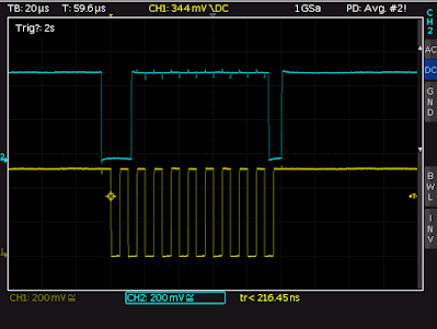
Midas Display - NACK to Read I2C Packet

The ninth bit (left MSB bit first) in the SCL clock train (yellow trace) in the above trace shows that the corresponding position in the SDA trace (blue trace) was high and therefore represents a negative acknowledgement (NACK) to the read command; the same bit position on the trace below has a low on the ninth bit (blue trace) represents an acknowledgement (ACK) to a write command.

Midas Display - ACK to Write I2C Packet

For further information, see Figures 6 and 7 in the TI document ‘Understanding the I2C Bus’ for waveforms relating to I2C ACK and NACK responses.

Code Changes
The code change mentioned in the above paragraph was implemented in the PSoC TestI2CAddress function located in 'main.c'. Other changes were made in main to suit the terminal program TeraTerm.

Testing Other Devices
To ensure the code change would work with other devices, two other I2C devices were tested; an Adafruit SI1145 light sensor and an INA219 current sensor

Test Setup - PSoC Development Board with SI1145 Sensor

Tera Term - I2C Address from SI1145 Sensor
Tera Term - I2C Address from SI1145 Sensor  

Test Setup - PSoC Development Board with INA219 Sensor

Tera Term - I2C Address from INA219 Sensor

Downloads and Disclaimer
The updated PSoC Creator project v1.1, for a PSoC4 device, can be downloaded as linked below. The original project is copyrighted and remains the property of Jörg Meier Software as noted in the project source.

I2CScan-v1_1.cywrk.Archive01.zip

Wednesday, 13 July 2022

PSoC Silicon ID Header File Creation

Summary
This blog offers a solution to generate PSoC header files from Cypress DAT files using PowerShell scripts. Available Cypress DAT files are merged and then converted into a single header file.

There is a thread similar to this post on the Infineon website called ‘JTAG/Silicon ID reference file’.

History
Fluctuations in global chip levels have resulted in a wider range of microcontrollers seen by companies responsible for programming and testing electronic hardware. 

To accommodate changes in microcontrollers using a more automated process for creating software header files, the scripts mentioned in this blog were designed. These scripts are fully functional, however, not without limitations as this is an initial foray into splitting scripts with this type of file content manipulation. 

The scripts were written in two parts because one script was made to run in the Program Files directory that contains the relevant DAT files. The second script was made to run with the merged DAT file.

Installation Requirement
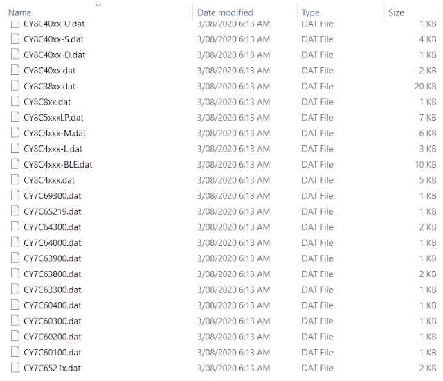
To access the DAT files, the Cypress (Infineon) PSoC Programmer should be installed. The DAT files are located at the following location - C:\Program Files (x86)\Cypress\Programmer\Devices

Example of Cypress .DAT File Listing

The DAT files contain various items of PSoC information. Of this, the device name and ID range are of primary interest. 

As an example for PSoC device CY8C4125AZI-473, the entry from file CY8C4xxx.dat is displayed below.

2,CY8C4125AZI-473, CY8C4125AZI-473, 48, 32768, 3, 04_2B_11_93, 04_2B_12_93, v33


Whether the PSoC ID is utilised to program PSoC devices or other information such as the size of the flash is needed for programming file verification, the PowerShell script could easily be adapted to suit these purposes.

Implementation
The first script called 'dat_merger.ps1' combines multiple DAT files using the PowerShell add-content command. The script was designed to handle all DAT files in the Cypress Programmer Devices directory however the script will also work on a single DAT file. 

Additionally, the first row in each DAT file is removed since this is redundant. To process the file in the next script, the merged file is saved in CSV format.

$dir = Get-Location
Write-Host "Merging Files"

$source ="$dir\*.dat"
$destination = "$dir\merge.csv"

# Remove first row and merge all files in directory
Get-ChildItem -Filter '*.dat' | ForEach-Object {
Get-Content $_ | Select -Skip 1 | Add-Content $destination
}


The second script dat_parser.ps1 removes any unwanted columns, selects only the first column of PSoC IDs, adds the text ‘#define’, formats the ID into a preferred value by stripping the formatting and then saves the result as a jtag.h file.

$dir = Get-Location
Write-Host "Parsing files in $dir"
# Grab merged csv files
$source = "$dir\merge.csv"
$destination ="$dir\jtag.h"

# Strip columns, add hash define and number format for each line, strip CSV then save as header file
Import-CSV-Delim ','$source -Header a,b, c, d, e, f, g |
Select "b","g" | ForEach-Object {$_."b" = "#define $($_."b")";$_} |
ForEach-Object {$_."g" = "0x$($_."g")";$_} |
ConvertTo-Csv -NoTypeInformation |
Select-Object -Skip 1 |
# Option for tab instead of spaces
#% { $_ -replace ‘_‘, “” -replace (‘,‘, "`t")  -replace ('"', '')} |
% { $_ -replace _‘, “” -replace (‘,‘, ''.padleft(10, ' '))  -replace ('"','')} |
Out-File $destination -Encoding utf8


Output
The first script would merge DAT files. Two example files were chosen CY8C42xx-D.dat and CY8C44xx.dat.

Before Script 

1,CY8C42xx-D, CY8C42xx-D, 8, 5, 128
2,CY8C4245PVI-DS402, CY8C4245PVI-DS402, 28, 32768, 3, 17_03_11_A7, v17
2,CY8C4245FNI-DS402, CY8C4245FNI-DS402, 25, 32768, 3, 17_02_11_A7, v17
2,CY8C4246PVI-DS402, CY8C4246PVI-DS402, 28, 65536, 3, 17_01_11_A7, v17
2,CY8C4246FNI-DS402, CY8C4246FNI-DS402, 25, 65536, 3, 17_00_11_A7, v17

1,CY8C44xx, CY8C44xx, 8, 5, 128
2,CY8C4A45PVI-481, CY8C4A45PVI-481, 28, 32768, 3, 1C_02_11_AC, v17
2,CY8C4A45FNI-483, CY8C4A45FNI-483, 45, 32768, 3, 1C_03_11_AC, v17
2,CY8C4A45LQI-483, CY8C4A45LQI-483, 48, 32768, 3, 1C_00_11_AC, v17
2,CY8C4A45AZI-483, CY8C4A45AZI-483, 48, 32768, 3, 1C_01_11_AC, v17
2,CY8C4A45FNQ-483, CY8C4A45FNQ-483, 45, 32768, 3, 1C_41_11_AC, v17
2,CY8C4A45LQQ-483, CY8C4A45LQQ-483, 48, 32768, 3, 1C_40_11_AC, v17

After Script 
2,CY8C4245PVI-DS402, CY8C4245PVI-DS402, 28, 32768, 3, 17_03_11_A7, v17
2,CY8C4245FNI-DS402, CY8C4245FNI-DS402, 25, 32768, 3, 17_02_11_A7, v17
2,CY8C4246PVI-DS402, CY8C4246PVI-DS402, 28, 65536, 3, 17_01_11_A7, v17
2,CY8C4246FNI-DS402, CY8C4246FNI-DS402, 25, 65536, 3, 17_00_11_A7, v17
2,CY8C4A45PVI-481, CY8C4A45PVI-481, 28, 32768, 3, 1C_02_11_AC, v17
2,CY8C4A45FNI-483, CY8C4A45FNI-483, 45, 32768, 3, 1C_03_11_AC, v17
2,CY8C4A45LQI-483, CY8C4A45LQI-483, 48, 32768, 3, 1C_00_11_AC, v17
2,CY8C4A45AZI-483, CY8C4A45AZI-483, 48, 32768, 3, 1C_01_11_AC, v17
2,CY8C4A45FNQ-483, CY8C4A45FNQ-483, 45, 32768, 3, 1C_41_11_AC, v17
2,CY8C4A45LQQ-483, CY8C4A45LQQ-483, 48, 32768, 3, 1C_40_11_AC, v17


Running the second script on the merged file output from the first script results in a new file called jtag.h as shown below.

#define CY8C4245PVI-DS402         0x170311A7
#define CY8C4245FNI-DS402         0x170211A7
#define CY8C4246PVI-DS402         0x170111A7
#define CY8C4246FNI-DS402         0x170011A7
#define CY8C4A45PVI-481         0x1C0211AC
#define CY8C4A45FNI-483         0x1C0311AC
#define CY8C4A45LQI-483         0x1C0011AC
#define CY8C4A45AZI-483         0x1C0111AC
#define CY8C4A45FNQ-483         0x1C4111AC
#define CY8C4A45LQQ-483         0x1C4011AC

One of the limitations with the current implementation is the uneven padding between the PSoC device name and the ID. The parser code inserts ten white spaces which may not conform with all programming styles.

Final Thoughts
The PowerShell scripts (under GPL) have been tested on several DAT files however the outputs should be verified as part of standard practice. Improvements are welcomed!

Downloads
 

Cypress Dat Merger PowerShell Script
dat_merger.ps1

Cypress Dat Merger PowerShell Script
dat_parser.ps1

Cypress Dat Merger PowerShell Script
jtag.h
(Example of PSoC4, PSoC5)


Thursday, 29 April 2021

Novel Voltage Interruption Tester for IEC 61496-1

Summary
This blog provides details of a novel voltage interruption tester that demonstrates the requirements listed in the IEC 61496-1 standard, section 4.3.2.2. 

The tester was needed because certain types of electronic hardware must be tested to the IEC 61496-1 standard and dedicated testing facilities have had reduced access during the pandemic. The purpose of the tester in this blog is preliminary testing which would not replace an authorised testing facility.

Description
The interruption test hardware described in this blog was designed for DC systems to 48 V and currents to 3 A. For design constraints, interruption timing was considered important, followed by access to available hardware then output voltage regulation.

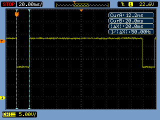
The capture below displays section 4.3.2.2 of the IEC standard which shows the timing of the three interruption tests.

Supply Voltage Interruptions

Hardware Solutions
Off the shelf power supply evaluation boards such as the Vishay SiC461 were tested initially. To control the output voltage, a programmable resistor replaced one of the feedback elements. By using a programmable resistor, a 10 ms pulse width was achievable. However, the output voltage rise and fall times were asymmetrical and several milliseconds in duration.

Alternative solutions utilising linear regulators such as the LM317T were analysed. The linear regulator produced very sharp output voltage rise and fall times. The limitation of the linear regulator was the LM317 voltage regulation and accompanying device heat dissipation.

By utilising existing resources, such as individual benchtop supplies, a simpler solution was identified. It was likely that workspaces would have access to one dual output or two single regulated adjustable power supplies. These supplies could be used together for the switching tests.

The hardware in the system consisted of a microcontroller (PSoC) that interfaced to a pair of optocouplers (4N28) in turn driving two high-side switches (BTS50085). The output of each high-side switch was tied together with series diodes (1N5404) to produce the output.

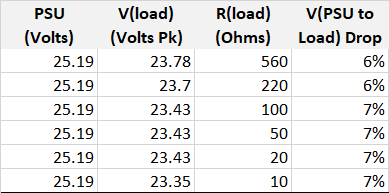
One design weakness using this solution was the supply to output voltage drop. As the cumulative voltage drop of the high-side switch and diode changed with load current, the power supplies required adjustment to achieve the correct test voltages.

Hardware Concept
Shown below was the original concept proof of the hardware. The high-side switch datasheet lists an operating voltage to some 58 V and a current of 11 A.

Interruption Tester Concept Hardware


Circuit Overview
Control signals generation was performed by a microcontroller; any type could perform the task as the signals are slow-moving. Two control signals from the microcontroller drive a set of optocouplers. For this design, an ancient pair of 4N28’s were fitted. 

The transistor output of the optocouplers switched the high-side driver inputs to 0 V. This was required as the inputs of the high-side drivers BTS50085 must be switched to 0 V to activate their outputs.

Microcontroller
An off the shelf CY8CKIT-059 Cypress development board implemented a PWM to drive two outputs for the optocouplers. 

The onboard switch and LED acted as the user interface. 

Repetitive switch presses selected a subsequent test. Flashes from the onboard blue LED indicated the test number. No flash for off, one flash for test one up to three flashes for test three.

For the top design in PSoC Creator, the first PWM output provided the timing for the voltage dip. The second PWM output configuration and some flip flops ensured that the half voltage was active before and after the first PWM changed state. Understandably there are other ways to use the PWM component, again this was a concept proof.

PSoC Creator PWM Test Setup

The PWM was configured as illustrated below. Settings were controlled from within the code.

PWM Component Setup
PWM Component Setup


The rise and fall times (10%, 90%) were 20 us and 90 us respectively
with the output driving a resistive load.

Rise Time for Resistive Load

Fall Time for Resistive Load

Output Waveforms
The following captures were taken when driving a resistive load.
 

Interruption Test 1 with Resistive Load
 

Interruption Test 2 with Resistive Load


Interruption Test 3 with Resistive Load

The next captures were taken when driving a DC 12 V fan.

Interruption Test 1 with DC Fan

Interruption Test 2 with DC Fan

Interruption Test 3 with DC Fan

Output Voltages
For the three interruption tests, various loads were tested and peak voltages measured.

Interruption Test 1 with Various Resistive Loads

Interruption Test 2 with Various Resistive Loads

Interruption Test 3 with Various Resistive Loads
 

The above test results show that adjustment to the power supply voltages was required to accommodate for the system voltage drop.

PSoC Code
Listed below is the test code for the PSoC controller.


/**
* @file main.c
* @brief Basic example of IEC61496-1 tests
* @version 0
*
* History
* Version       Change Notes
* 0.0           Test code
*/

#include <project.h>
#include <stdbool.h>

/* Prototypes */
void led_flash_state(uint8 state_num);


/**
* @brief Flash LED
* @param state
*/
void led_flash_state(uint8 state_num)
{   
    while (state_num != 0)
    {
        LED_Write(true);
        CyDelay(250);
        LED_Write(false);
        CyDelay(250);
        state_num--;
    }
}

/**
* Main
*/
int main()
{                       CyGlobalIntEnable;

    
uint8 state = 0;
    uint8 state_update = false;
    
    for(;;)
    
{
    if (SW1_Read()== false)
    {
        CyDelay(200);         /* Some debounce */
        
state++;
        state_update = false;
        if (state == 4)      /* Toggle states */
        {
            state = 0;
        }
    }

    if ((state == 0) && (state_update == false))
    {
        PWM_Stop();
        state_update = true;          /* No PWM in first state */
    }
    
    if ((state == 1) && (state_update == false))
    {
        PWM_Stop();                     /* Test 1 - 10 ms 100% dip */
        PWM_WritePeriod(999u);
        PWM_WriteCompare1(110u);        /* Control PWM output 1 */  
    
    PWM_WriteCompare2(0u);
        PWM_WriteControlRegister(PWM_CTRL_ENABLE);
        PWM_Start();
        led_flash_state(state);
        state_update = true;
    }

    if ((state == 2) && (state_update == false))
    {
        PWM_Stop();                      /* Test 2 - 20 ms 50% dip */
        PWM_WritePeriod(1999u);
        PWM_WriteCompare1(200u);
        PWM_WriteCompare2(210u);         /* Control PWM output 2 for lower voltage */         PWM_Start();
        led_flash_state(state);
        state_update = true;
    }

    
if ((state == 3) && (state_update == false))
    {
        PWM_Stop();                      /* Test 3 - 500 ms 50% dip */
        PWM_WritePeriod(49999u);
        PWM_WriteCompare1(5000u);
        PWM_WriteCompare2(5010u);        /* Control PWM output 2 for lower voltage */         led_flash_state(state);
        state_update = true;
    }
  }
}

/* End */


Summary
For concept proof, the tests using high-side switches controlled by a microcontroller verified specific requirements detailed in the IEC 61496-1 standard. During tests, the input to output voltage drop was less than 10 %. Compensation for voltage drop was achieved by adjusting power supply voltages.

Depending on design requirements, a different microcontroller, high-side switches with a lower operating voltage, or alternative components could be selected. If isolation from the switched output voltage was not a consideration, the optocouplers could be omitted.

With access to testing facilities being limited, having the hardware to provide preliminary on bench verification can be a consolation.

Downloads
The PSoC Creator 4.4 project and schematic from the Top Design are available for download.

PSoC Creator Top Design Schematic

PSoC Creator 4.4 Project

Sunday, 29 November 2020

Model Rocket Launcher Bluetooth Android Part 2

Summary
This blog details hardware and code changes to the Bluetooth PSoC Model Rocket Launcher for monitoring battery voltage and current. The current monitoring output provided by the high side switching device was measured and calibrated using multi-point characterisation in the launcher’s PSoC controller.

Purpose of Monitoring
Under-voltage battery monitoring was included to minimise the chance of battery over-discharge. The battery voltage for a
25% State of Charge (SoC) was used as a reference in the rocket launcher firmware.

Measurement and monitoring of the current drawn by the igniter were included to check the recommended all-fire current of 2 A (Estes forum) was reached during a launch.

Battery Voltage
A hardware connection for monitoring the battery voltage, using a Cypress PSoC ADC input, was not part of the initial circuit board design (PCB).

Rocket Launcher PCB with Strapped Battery ADC Input

As the PCB included hardware for a voltage divider across the batter, a connection was required to a spare PSoC pin with ADC capability. In the image above a wire was strapped from the voltage divider to the ADC input.

Launcher Battery Voltage Divider

The resistor values selected for the voltage divider were changed to use values already available in the design. Assuming a battery charged to 13.8 V, the voltage at the ADC input, taking into account the loss in the reverse protection Schottky diode D6, was approximately 2.4 V.

For the PSoC SAR ADC reference voltage, the VDDA supply pin on the PSoC was used.

It should be noted that the battery voltage measurement was for indicative purposes only. To improve ADC measurement accuracy, the ADC reference voltage could be changed to utilise the PSoC internal 1.024 V reference. Adjustment to the battery voltage divider would be required.

Launcher SAR ADC Configuration

Igniter Current
The high side switching device (VN7040) features an output which provided a voltage representation of the current measured by the VN7040. A
PSoC ADC input was used to measure the voltage.

Launcher Battery Current Sense Output
Launcher Battery Current Sense Output (MSense)

The value of the resistor connected to the output of the high side switch (MSense) was reevaluated to suit an Estes igniter. Assuming losses in the circuit such as cabling (resistive), reverse protection diode forward voltage (477 mV @ 15A), the high (40 mR) and low side (30 mR) switching devices MOSFET resistances. A full charged lead-acid battery driving an igniter (Estes 800 mR) with the resistive losses should result in a current of slightly over 10 A.

VN7040 K-Factor vs Isense Response (Courtesy ST)

As the operating current was expected to be above 4.5 A, the K factor of 1340 was selected from the VN7040 datasheet.

VN7040 Current Sense K Factor > 4.5 A

There were two caveats for calculating the current sense resistor value. Firstly, under normal operating conditions the voltage generated across the current sense resistor should be less than the ADC maximum voltage. For the existing design, the SAR ADC reference voltage was 5 V so this was not a primary concern. The maximum voltage should be reviewed if the ADC reference voltage was changed to 1.024 V. Secondly, the maximum current output by the sense output (MSense) of the high side switches was listed as 10 mA.

VN7040 Current Sense Output Max Operating Characteristics

Selecting a current of 10 A and a nominal k factor of 1340, the formula shown in Table 11 of the VN7040 data sheet was applied.

VN7040 Truth Table with Current Sense Formula

Applying the formula shown in the truth table pictured above, an Isense value of 7.46 mA was yielded.

VN7040 Isense Calculation

With a maximum ADC reference voltage of 5 V, a 590 R resistor was selected. The maximum voltage at the PSoC ADC pin, being the product of the Isense value and the resistor value, gave approximately 4.4 V.

ADC Configuration
The SAR ADC was configured for two channels, 12-bit with a conversion time of approximately 2 ms.

PSoC SAR ADC Setup
PSoC SAR ADC Setup

The results from the SAR ADC, battery voltage and current sense (voltage), were converted into millivolts.

static uint16_t    adc_result_multiplier     = 23u;
static uint16_t    adc_result2_multiplier    = 554u;
static uint16_t    adc_result_divider       = 10u;
static uint16_t    adc_result2_divider   = 100u;
static uint16_t    adc_result_trim      = 154u;

adc_result1 = ADC_SAR_CountsTo_mVolts(0,ADC_SAR_GetResult16(0));
adc_result2 = ADC_SAR_CountsTo_mVolts(1,ADC_SAR_GetResult16(1));
adc_voltage_result = (adc_result2 * adc_result2_multiplier)/adc_result2_divider;
adc_current_result= ((adc_result1 * adc_result_multiplier)- adc_result_trim)/adc_result_divider;

To calibrate the PSoC ADC current measurement, a multi-point characterisation was performed. Various resistive loads were used in place of the igniter and the ADC result recorded.

PSoC ADC Raw Data from Resistive Loads with Power Supply

The ADC result was output on the serial port. ADC results were plotted against the measured current to produced the graph displayed below.

Measured Current vs PSoC ADC Voltage for Various Resistive Loads

ADC Data Serial Output
The ADC results were output on the Rocket Launcher serial port. The data was transmitted at a rate of 921,600 baud to an Android phone which was running the application Serial USB Terminal. Written by Kai Morich, the application was one of the few which supported higher baud rates and was stable at that data rate.

Serial USB Terminal Android Application Landing Screen

Shown in the capture above is the Android phone application. Connection of a USB to TTL adaptor from the launcher to the Android phone was achieved using an On The Go (OTG) adaptor cable.

Serial USB Terminal Android Application Settings Screen

Configuration for the 921,600 baud rate was achieved through the settings tab in the application.

Serial data was captured for two supply types, the first a benchtop Rigol linear power supply and the second a lead-acid battery (1.2 AH).  The graph shown below provides the ADC measurement plotted against various resistive loads.

PSoC ADC Voltage vs Resistive Load

Bench testing with resistive loads showed that ADC measurements were stable. The graph below shows the ADC current measurement when testing with a 5 R load.

PSoC ADC Voltage Samples for Resistive Load of 5R

Low Battery and Current Error States
The ADC result from the battery voltage measurement was compared to a threshold of 12 V for the under-voltage detection. Similarly, for the under-current detection, the current measurement was compared a value of 0.558 V which represented approximately a current of 2 A.

    
if (SYSTEM_FLAGS_ADC.adc_has_result == true)
{   
/* Order of execution sets priority */
    if (adc_voltage_result < under_voltage_compare)
    {
        Error_State = under_voltage;
    }
    else if (adc_current_result < under_current_compare)
    {
        Error_State = under_current;
    }
}

OLED Screen Update
Additional error states relating to the low battery voltage and low igniter current were added to the rocket launcher firmware.

The OLED screen below was shown after the rocket launch cycle if the battery voltage fell below 12 V during the launch.

Rocket Launcher OLED Low Battery Screen

For the low current, the screen below was displayed after the rocket launch cycle, if the measured current fell below approximately 2 A during the launch.

Rocket Launcher OLED Low Current Screen

Field Testing
Field rocket launches were performed to capture ADC results with Estes igniters. There were multiple events which caused the ADC results to vary of which some events were intrinsic to the igniter behaviour during a launch.

The graph below represents one of the instances where the launch of the rocket was successful however, the igniter wires shorted moments after liftoff. The constant current draw of the shorted wires is represented by the constant high from time 53 s.

Rocket launcher igniter current toggling at start
Rocket Launcher Igniter Current Toggling

Field Launches
Below are snippets from recent launches.

Estes Curvilinear model rocket with standard size A engine.

Estes Fat Boy model rocket with standard size A engine.

Unbranded model rocket.


Final Thoughts
The hardware and firmware updates performed to the rocket launcher provided additional features and monitoring. Specifically, monitoring the igniter current provided insight into the different events and responses which can occur to the igniter on the launchpad. In a future release, a scheme for current monitoring would involve the development of the firmware to handle the various igniter responses.

Downloads
The
updated firmware for the PSoC launcher project.

Rocket Launcher PSoC Project rev 1.03