Showing posts with label port. Show all posts

Tuesday, 8 November 2022

EPEVER MPPT to PC using RS485 or WiFi

Introduction
This blog provides two methods for connecting an EPEVER MPPT with RS485 capability to a Windows PC running Solar Station Monitor.
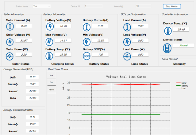
EPEVER Solar Station Monitor

Direct Connection
Direct connection utilises hardware consisting of an FTDI USB to RS485 adaptor, part USB-RS485-WE with an RJ45 male to screw terminal adaptor to connect to the EPEVER MPPT.

Details for the various connections using the FTDI adaptor are pictured below.

RS485 connections A, B and 0 V were used; no termination resistor was added to the circuit.

FDTI RS485 to EPEVER MPPT

Wired USB FTDI to RJ45 adaptor.

FDTI RS485 to RJ45 8-Way Screw Terminal for EPEVER MPPT

FTDI adaptor wiring from USB-RS485-WE manual.

USB-RS485-WE Connections (Courtesy FTDI)

 Pinout for RJ45 connector.

RJ45 Pinouts
RJ45 Pinouts (Courtesy Huawei)

There were no requirements to change the Windows setup for the FTDI adaptor. This device appears as a standard COM port. This COM port was then selectable in the EPEVER Solar Station Monitor application.

Wireless Connection
The wireless connection makes use of an Elfin EW11A. This device bridges RS485 and wireless station and or access point.
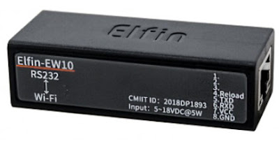
Elfin EW11A (Courtesy Hi-Flying)

Also used in the hardware solution was the optional Elfin adaptor cable. For connecting to the EPEVER MPPT, an RJ45 male to screw terminal adaptor was utilised. Since the EW11A requires DC 5 V, an further connection to a power supply is also required.
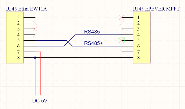
 

Elfin EW11A to EPEVER MPPT

Elfin EW11A to RJ45 8-Way Screw Terminal

The computer running EPEVER Solar Station Monitor required a software Ethernet to COM port bridge. The HW Virtual Serial Port application from HW-Group was used.
Side note. The EPEVER WiFi 2.4 G RJ45 A adaptor was tested separately however because WiFi Station mode was required, the EPEVER was not suitable.


Elfin EW11A Setup

This tests in this blog were geared towards verifying that wireless communications with the MPPT were practicable. The final goal was to interface the EPEVER with Home Assistant.

Using the I.O.T Workshop application from High-Flying, the EW11A was configured for station mode, TCP server and the port settings were configured for consistency with Home Assistant. Ethernet port number 8899 (MQTT) was used. The Comment and Application Guide from Eniris was used as the primary reference document.

Removed from the screen capture below are the login details (admin and password), wireless station ID and associated password.
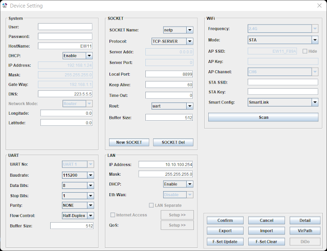
EW11A Device Setup for EPEVER MPPT Using I.O.T Workshop

No UART protocol was selected. Telnet was disabled and web interface was kept enabled.

EW11A Device Detail for EPEVER MPPT Using I.O.T Workshop

The UART settings 115200, 8, N, 1 were left as default.
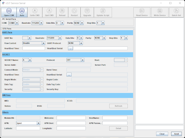
EW11A Serial Setup for EPEVER MPPT Using I.O.T Workshop

Virtual Serial Port
For this blog the
HW Virtual Serial Port application from HW-Group was used. The default configuration of the application required changes. For example, if the option Network Virtual Terminal (NVT) was enabled, communications with the EPEVER MPPT were sporadic or only specific values were received correctly. Other tools offering an Ethernet to COM virtual com port may offer similar configuration options which should be validated.

HW Virtual Serial Port Settings for EPEVER MPPT  and Elfin EW11A
HW Virtual Serial Port Settings for EPEVER MPPT and Elfin EW11A

Shown on the Virtual Serial Port page is the IP and port for the Elfin EW11A.
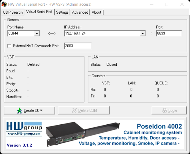
HW Virtual Serial Port Page for EPEVER MPPT with Elfin EW11A

With the Elfin EW11A configured and powered, clicking Create COM in the virtual serial port application established the Ethernet link. Shortly after COM4 appeared in Windows Device Manager.

Serial Port Created Using HW Virtual Serial Port

With a connection established to the EW11A and the EPEVER MPPT, the EPEVER application could communicate with the MPPT. This was indicated by the change in counter values (Rx and Tx).

HW Virtual Serial Port Connected to EPEVER MPPT with Elfin EW11A

Solar Station Monitor
No changes were made to the setup of the EPEVER Solar Station Monitor application other than configuring the required COM port to communicate with the Virtual COM port.
The default port settings were used.
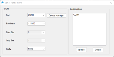
EPEVER COM Port Settings
 

After clicking Start Monitor in the application, data was exchanged within a few seconds.

The capture below was taken after sunset with the MPPT load active.

EPEVER Solar Station Monitor (Load Active)

The capture below was taken during sunlight hours.

EPEVER Solar Station Monitor (During Daylight)


For the capture below, the EPVER monitoring tool was restarted to capture the transition between load OFF and ON.

EPEVER Solar Station Monitor Graphed Data Showing Load ON

EPEVER Solar Station Monitor Graphed Data Showing Load OFF

Final Thoughts
This post offered two methods for connecting an EPEVER MPPT with a Windows PC running Solar Station Monitor application. The WiFi connection and subsequent testing using the Elfin EW11A served as preliminary work to develop a dedicated circuit board to bridge the EW11A with the EPEVER MPPT.

Wednesday, 15 February 2017

MCP23S17 IO Port Expander Header File / Register

Summary
For a recent project the 16bit IO Expander, MCP23S17, from Microchip was enlisted for low voltage input scanning. 

Searching online, at the time of writing this blog, there were no projects using this part with sample code. 

Below is the header file that may be of use.


MCP23S17 Microchip IO Expander QFN Package
Microchip IO Expander QFN Package


Downloads


mcp23s17.h

Code


/******************************
* mcp23s17.h
******************************/

#ifndef mcp23s17_h
#define mcp23s17_h

typedef unsigned char   uint8;
    
#define MCP_READ   0x41     /* Read */
#define MCP_WRITE   0x40     /* Write */
#define Mode_8Bit     1         /* Addressing 8/16bit */
#define Mode_16bit    0

#ifdef Mode_16Bit
    /******************************
    * Control register for BANK=0
    ******************************/
    #define IODIRA        0x00      /* Data Direction Register for PORTA */
    #define IODIRB        0x01      /* Data Direction Register for PORTB */ 
    #define IPOLA         0x02      /* Input Polarity Register for PORTA */ 
    #define IPOLB         0x03      /* Input Polarity Register for PORTB */ 
    #define GPINTENA      0x04      /* Interrupt-on-change enable Register for PORTA */ 
    #define GPINTENB      0x05      /* Interrupt-on-change enable Register for PORTB */ 
    #define DEFVALA       0x06      /* Default Value Register for PORTA */    
    #define DEFVALB       0x07      /* Default Value Register for PORTB */      
    #define INTCONA       0x08      /* Interrupt-on-change control Register for PORTA */  
    #define INTCONB       0x09      /* Interrupt-on-change control Register for PORTB */      
    #define IOCON         0x0A      /* Configuration register for device */                      
    #define GPPUA         0x0C      /* 100kOhm pullup resistor register for PORTA (sets pin to input when set) */    
    #define GPPUB         0x0D      /* 100kOhm pullup resistor register for PORTB (sets pin to input when set) */      
    #define INTFA         0x0E      /* Interrupt flag Register for PORTA */        
    #define INTFB         0x0F      /* Interrupt flag Register for PORTB */    
    #define INTCAPA       0x10      /* Interrupt captured value Register for PORTA */  
    #define INTCAPB       0x11      /* Interrupt captured value Register for PORTB */    
    #define GPIOA         0x12      /* General purpose I/O Register for PORTA */  
    #define GPIOB         0x13      /* General purpose I/O Register for PORTB */ 
    #define OLATA         0x14      /* Output latch Register for PORTA */ 
    #define OLATB         0x15      /* Output latch Register for PORTB */
#endif

#ifdef Mode_8Bit
    /******************************
    * Control register for BANK=1
    ******************************/
    #define IODIRA        0x00      /* Data Direction Register for PORTA */
    #define IPOLA         0x01      /* Input Polarity Register for PORTA */  
    #define GPINTENA      0x02      /* Interrupt-on-change enable Register for PORTA */     
    #define DEFVALA       0x03      /* Default Value Register for PORTA */    
    #define INTCONA       0x04      /* Interrupt-on-change control Register for PORTA */     
    #define IOCONA        0x05      /* Configuration register for device */          
    #define GPPUA         0x06      /* 100kOhm pullup resistor register for PORTA (sets pin to input when set) */     
    #define INTFA         0x07      /* Interrupt flag Register for PORTA */
    #define INTCAPA       0x08      /* Interrupt captured value Register for PORTA */
    #define GPIOA         0x09      /* General purpose I/O Register for PORTA */  
    #define OLATA         0x0A      /* Output latch Register for PORTA */ 
    #define IODIRB        0x10      /* Data Direction Register for PORTB */ 
    #define IPOLB         0x11      /* Input Polarity Register for PORTB */ 
    #define GPINTENB      0x12      /* Interrupt-on-change enable Register for PORTB */
    #define DEFVALB       0x13      /* Default Value Register for PORTB */      
    #define INTCONB       0x14      /* Interrupt-on-change control Register for PORTB */
    #define IOCONB        0x15      /* Configuration register for device */  
    #define GPPUB         0x16      /* 100kOhm pullup resistor register for PORTB (sets pin to input when set) */        
    #define INTFB         0x17      /* Interrupt flag Register for PORTB */    
    #define INTCAPB       0x18      /* Interrupt captured value Register for PORTB */    
    #define GPIOB         0x19      /* General purpose I/O Register for PORTB */ 
    #define OLATB         0x1A      /* Output latch Register for PORTB */
#endif
    
/* Config bits - IOCON */
#define BANK  0x80
#define MIRROR  0x40
#define SEQOP  0x20
#define DISSLW  0x10
#define HAEN  0x08
#define ODR      0x04
#define INTPOL  0x02

/******************************
* Prototypes
******************************/
void MCP23S17_init();
void MCP23S17_write(uint8 address, uint8 value);
uint8 MCP23S17_read(uint8 address);
uint8 MCP23S17_verify(uint8 address, uint8 verify_data);
    
#endif
/* END */


Change Summary

Version 1.00 (10 February 2017)

  • Created register mapping for MCP23S17, 8 and 16 bit modes