Sunday, 30 April 2023

Salvaging from LG Controller Board EBR369328

Introduction
This microblog reviews the electronic components (parts) that could be salvaged from an LG air conditioner compressor inverter controller board.
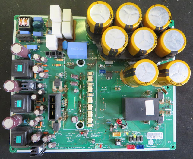

LG Control Board EBR369328 Top Side

Summary
After being provided with the inverter controller board for spare parts, it seems relevant to detail salvageable electronic components in this blog.

Being unfamiliar with air conditioning (AC) equipment, AliExpress was used to identify the function which is listed as an LG three-phase inverter compressor (motor) control board.

It should be noted that the LG control board was supplied not working. In these instances when salvaging electronic parts, additional
testing and diligence should be taken.

Salvageable Top Side Components
For the current measurement on the three-phase supply, an Allegro device capable of + 50 A, part number ACS756 was utilised. The Allegro part is listed as obsolete however this does not prevent is being used again for testing a
design concept. This is one of the devices that should be tested once removed because of its use in the circuit.
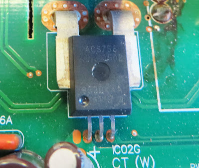
Allegro ACS756
Allegro ACS756

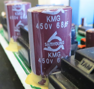
The bulk of the electrolytic capacitors are manufactured by the Korean company, Samyoung. Some of the electrolytic through-hole capacitors associated with the mains (line) supply may be handy for spares if mains voltage projects are an area of interest.

Mains Rated Electrolytic Capacitor

The large 10 to 20 W wire-wound ceramic resistors had no signs of overheating or physical damage. These resistors may be worth salvaging even for simple dummy loads.
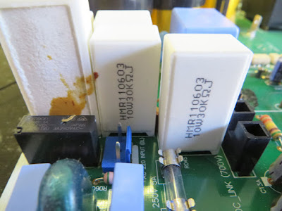
Wirewound Resistors
Wirewound Resistors

Located near the wire-wound resistors are mains capacitors manufactured by the Korean company, Pilkor. On this LG board, those capacitors were in excellent condition and worth salvaging.

Mains Capacitors
Mains Capacitors

The large vertical connector, AMP series D-5200, should be considered for anyone involved with high-current designs.

AMP Connector D-5200

The circuit board is fitted are a few different types of optocouplers. One of the interesting parts is the HCNR201 which is a high-linearity optocoupler from Broadcom.
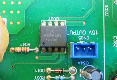
Broadcom HCNR201
Broadcom HCNR201

Other optocouplers include Toshiba TLP781, TLP559 and TLP521. All these Toshiba optocouplers are obsolete however they may serve well as spares or for repair purposes.

Various Toshiba Optocouplers

A TE relay with the part number T92S7D12-12 is fitted to the board. This relay is rated at a 12 V at 20 A and is still actively manufactured by TE.

High Current TE Relay

Contained on the board are a plethora of remaining components to consider for salvage. These include an oscillator, heatsinks, LEDs, chokes, axial resistors and unidentified components.

Salvageable Bottom Side Components
Fitted on the bottom side of the PCB is the motor switching module (IGBT). This device is most likely not worth salvaging.

Motor Driver Module
Motor Driver Module

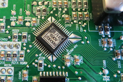
The semiconductors on the bottom side appear to have no identification markings or those markings have become obscured by what appears to be a protective (conformal or lacquer) coating.
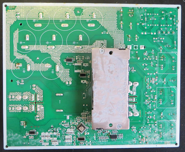
LG Control Board EBR369328 Bottom Side

All electronic parts on the bottom side of the board are epoxy glued to the as part of the circuit board assembly process. There is little to salvage from this side of the board because of the glue although removing components is possible with the correct tools. For low-cost and high-throughput printed circuit board assemblies, soldering using wave solder in a single pass has been a common manufacturing method. This LG board employs some solder-thieving designs in the circuit board layout as pictured below.
Component with Solder Thieving Pads

Sunday, 16 April 2023

Voltage Interruption Tester for EN 61000-4-29 Updated

Introduction
This blog continues from a prior post, Voltage Interruption Tester for IEC 61496-1 Part 5. The interruption tester code detailed in that post was updated to suit supply dips or interruptions specifically to meet the standard EN 61000-4-29.

This original project was posted as a novel example of testing for changes in voltage. However, as interest in this project has been increasing specifically for the DC tests listed in the standard EN 61000-4-29, the code was changed to perform these tests only.

Code Changes
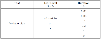
Code changes were implemented in the interruption tester for a closer approximation of EN 61000-4-29 and to improve the code portability between Infineon (Cypress) processors. In the EN 61000-4-29 standard, five tests are listed for DC voltage dips with fixed times of 10 ms to 1 s. An extract from the standard is shown below.

DC Voltage Dip Table from EN 61000-4-29

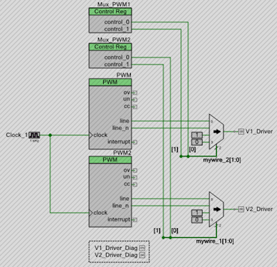
The PWM functionality in the Infineon microcontrollers, configured through the PWM component, was disabled.

Interrupt Tester Project Disabled PWM Logic

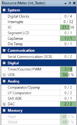
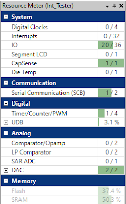
For the reduction in resources controlling the output pins between Cypress PWM and software output control, the Universal Digital Blocks (UDBs) dropped by almost 50 %.

Previous Project PSoC Resource Usage

Updated Project PSoC Resource Usage

The system timer was used as the replacement for the PWM component. Output pins that were PWM controlled are controlled directly in code. To improve the output waveform timing accuracy, the system timer was reconfigured from 10 ms to 1 ms.

Testing Code Changes
Timing control of the outputs controlling the load was performed in the corresponding function listed below.

/** *****************************************************************************
* Function Name: Output_Handler
*
* @brief Run interruption tests with timing below, 10 s separation between tests
*   Test 1 - 10 ms
*   Test 2 - 30 ms
*   Test 3 - 100 ms
*   Test 4 - 300 ms
*   Test 5 - 1000 ms
*
* @return none
****************************************************************************** */
void Output_Handler(uint8_t output_CurMenuItem, uint8_t out_statemachine)
{
    static uint8_t output_savedMenuItem;
    static uint8_t output_driver_state;
    
    if ((out_statemachine == OUTPUT_ON) && (output_CurMenuItem != 0))
    {       
        /* Handle PWM 1 Settings */
        if ((output_driver_state == OUT_OFF) || ((output_driver_state == OUT_LOW) && ( Pulse_Low_Ctr == 0)))
        {
            Pulse_High_Ctr = PWMValues[output_CurMenuItem].COMPARE1;
            Pulse_Low_Ctr = 0;
            output_driver_state = OUT_HIGH;
            V1_Driver_Write(true);
            V2_Driver_Write(true);
        }
        else if ((output_driver_state == OUT_HIGH) && ( Pulse_High_Ctr == 0))
        {
            Pulse_Low_Ctr = PWMValues[output_CurMenuItem].PERIOD1;
            output_driver_state = OUT_LOW;
            V1_Driver_Write(false);
        }
        output_savedMenuItem = output_CurMenuItem;
    }
    else if (out_statemachine != OUTPUT_ON)
    {
        V1_Driver_Write(false);
        V2_Driver_Write(false);
        output_driver_state = OUT_OFF;
    }
}


The standard EN 61000-4-29 standard states requirements for the rise and fall times when the tester is driving a 100 R load (
1 us to 50 us).

Test Generator Requirements from EN 61000-4-29

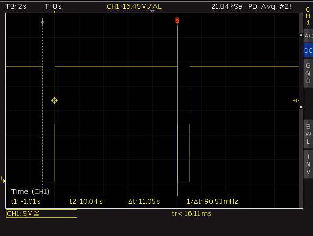
The pulse duration and time between tests were validated with the load.

10 ms Interruption Tester Output
 
100 ms Interruption Tester Output

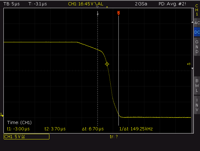
Testing showed that measured rise times were less than 18 us and the fall time less than 7 us.

Rise Time 10-90 % with 100 R Load

Fall Time 10-90 % with 100 R Load

Future Changes
To facilitate other microcontrollers, another revision of the display circuit board without capacitive sensing, a flat flex inter-board connection, watchdog and adding a third channel to the power board will be investigated.

Downloads
Listed below is the PSoC Creator project.

Interruption Tester 0.1c PSoC Project